+VCC_CPU
+VCC_CPU
+VCC_CPU
+VCC_CPU
+VCC_CPU
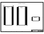
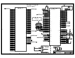
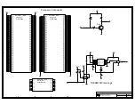
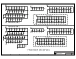
INTEL(R) E7500 CHIPSET CUSTOMER REFERENCE SCHEMATICS
R
D
C
B
B
D
C
1
1
2
3
4
5
6
7
8
2
3
4
5
6
7
8
A
A
LAST REVISED:
1900 Prairie City Road
Folsom, California 095630
TITLE:
Platform Apps Engineering
SHEET
03/04/02
+VCC_CPU
P24
P22
P20
P18
P16
P14
P12
P10
P8
P6
P4
P25
P23
P21
P19
P17
P15
P13
P11
P9
P7
P5
P3
P1
P2
ITP32B TAP
+VCC_CPU
TDO
TDI
TDO
TDI
P1
ITP
1-2 = P0 Only
2-3 = P0 + P1
Debug
Port
TDI
TDO
P0
JP3
ITP USE DIAGRAM
Place these resistors
near J18 (Processor 0)
VREF circuits for GTL+
Place these termination
resistors at the ends of the traces.
R7
7
51
51
R8
7
ICH3_A20M_N
4,6,53
ICH3_IGNNE_N
4,6,53
4,6,80
CPU_LINT1_NMI
4,6,53
CPU_STPCLK_N
4,80
CPU1_SMI_N
6,80
CPU0_SMI_N
R
1027
51
51
R
1028
ICH3_INIT_N
4,6,53,66
R7
4
200
CPU_BPM3_N
4,6
CPU_BPM2_N
4,6
R8
1
51
4,6
CPU_BPM1_N
R7
9
51
51
R8
0
51
R7
8
R8
6
1%
75
4
ITP_TDO_P1
1.
5K
1%
R8
5
ITP_TDI_P1
4
6
ITP_TDO_P0
2
3
1
JP3
ITP_TDI_P0
6
24
22
20
18
16
14
12
10
8
6
4
25
23
21
19
17
15
13
11
9
7
5
3
1
2
J13
0
R59
R60
0
0
R63
R89
0
C6
7
1U
F
1U
F
C6
8
C6
5
1U
F
1
U
F
C6
6
ITP_TMS_P
4,6
DBR_RESET_N
64
ITP_TRST_N
4,6
27.
4
1%
R8
8
200
R
838
R7
6
200
200
R7
5
200
R7
3
R7
2
200
200
R7
1
R7
0
200
100
1%
R6
1
R
6
2
1%
49.
9
CPU_BPM4_N
4,6
CPU_BPM5_N
4,6
FSB_CPURST_N
4,6,10
ITP_TCK_P
4,6,9
ITP_TCK_P
4,6,9
CPU1_GTL_VREF2
4
STPPWR
ITP_BCLK1
65
ITP_BCLK0
65
CPU0_GTL_VREF1
6
CPU0_GTL_VREF2
6
CPU1_GTL_VREF1
4
49.
9
1%
R6
5
R6
4
1%
100
R6
7
1%
49.
9
100
1%
R6
6
49.
9
1%
R6
9
R6
8
1%
100
4,6
CPU_BPM0_N
ICH3_LINT0_INTR
4,6,53
ICH3_CPUSLP_N
4,6,53
200
R
1026
9
Summary of Contents for Xeon
Page 24: ...Introduction 24 Design Guide This page is intentionally left blank ...
Page 30: ...Component Quadrant Layout 30 Design Guide This page is intentionally left blank ...
Page 52: ...Platform Clock Routing Guidelines 52 Design Guide This page is intentionally left blank ...
Page 66: ...System Bus Routing Guidelines 66 Design Guide This page is intentionally left blank ...
Page 118: ...Intel 82870P2 P64H2 118 Design Guide This page is intentionally left blank ...
Page 146: ...I O Controller Hub 146 Design Guide This page is intentionally left blank ...
Page 148: ...Debug Port 148 Design Guide This page is intentionally left blank ...
Page 210: ...Schematic Checklist 210 Design Guide This page is intentionally left blank ...
Page 220: ...Layout Checklist 220 Design Guide This page is intentionally left blank ...
Page 222: ...Schematics 222 Design Guide This page is intentionally left blank ...


