


Page 29
EN
Chapter 6 Installation
10. When the correct water quantity has been set, release
the “Water inlet” button and reconnect the internal
water hose to the yellow mixing zone.
!
WARNING
Water jet.
Risk of injury and risk of property damage due to es-
caping water.
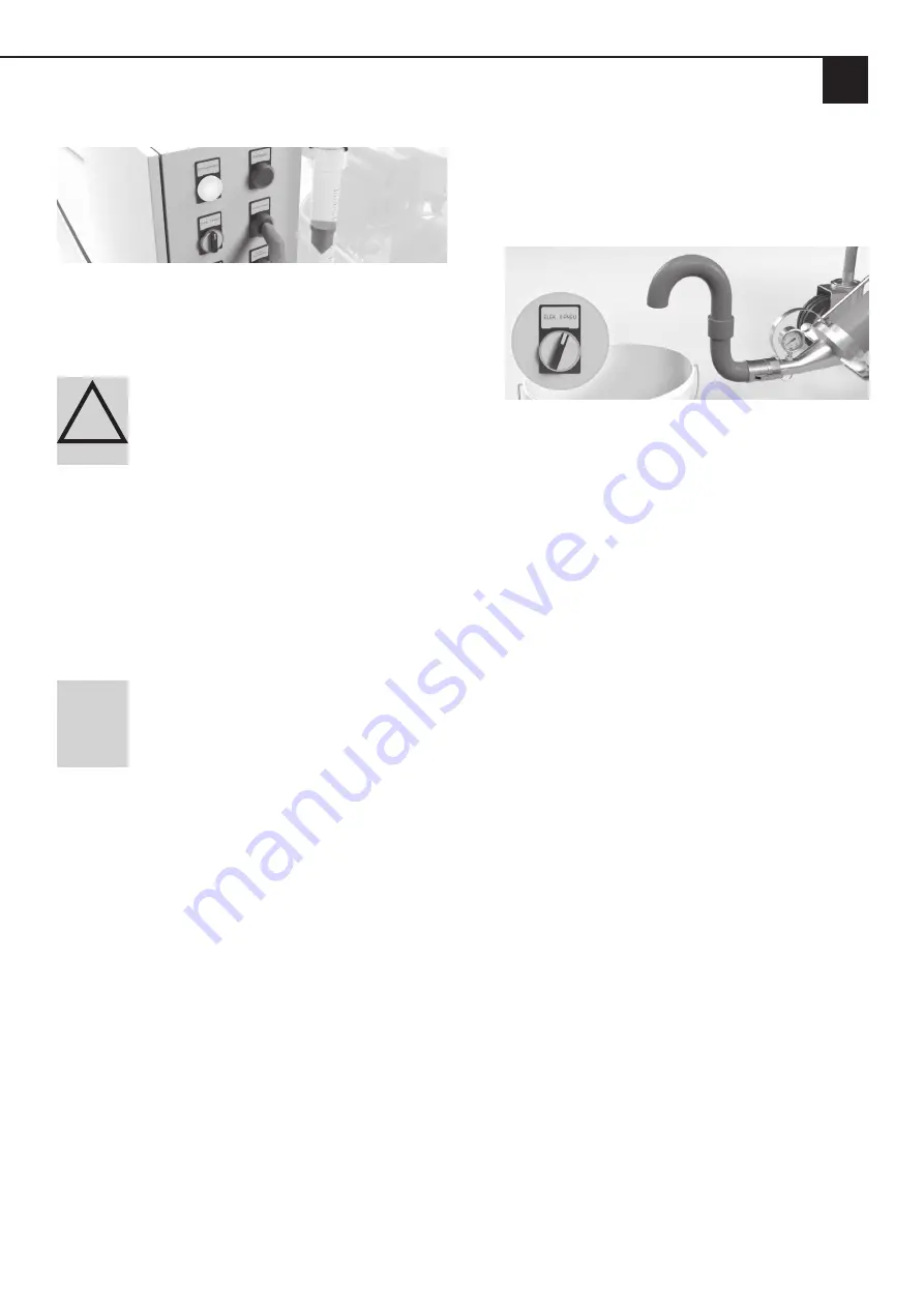
1. Interrupt the external water supply by closing the water
valve.
2. In order to release the pressure (approx. 2.5 bar), open
the water drainage valve on the water measuring sys-
tem under the pressure reducer.
3. Remove the hose from the external water supply.
4. Do not point the water jet at other people or yourself.
NOTE
After the end of work (especially if there
is a risk of frost), the residual water still in the water
measuring system should be drained either via the
water drainage valve below the pressure reducer or
below the water inspection glass.
6.7 Starting the machine
1. Open both cam levers of the mortar coupling at the
pump outlet (directly after the mortar pressure gauge).
2. Insert the male part of the starting hose (optional) into
the mortar coupling and close both cam levers.
3. Press the “Water inlet” button and fill the lower part of
the yellow mixing zone with some water (add water!)
and then release the button.
4. Now add only enough dry material to the material hop-
per until the lower part of the material hopper is full.
5. Then turn the start switch to pneumatic control “PNEU”.
The machine then switches on and the material mixed
with water comes out of the start-up hose (place a suit-
able container underneath to collect the material).
6. Then turn the start switch to “0”. The machine will
stop. Now the material hopper can be filled further
with dry mortar.
7. Now turn the start switch to “PNEU”. The machine then
switches on again and the correct (or required) material
consistency can now be set by turning the needle valve.
8. Turn the start switch to “0”. The machine will stop.
Then remove the start-up hose and clean it with water.
9. Before connecting the mortar hoses to the machine,
ensure that they are free of residual materials.
10. Fill approx. 2 to 3 litres of lime milk or wallpaper paste
into the mortar hose as pre-lubrication and then con-
nect it to the mortar coupling of the machine. If neces-
sary, extend the mortar hose and air hose to the desired
and appropriate delivery range/delivery height.
11. Connect the air hose to the GEKA coupling of the air
fitting.
12. Assemble the appropriate spray head or glue gun to
the end of the mortar hose and also connect the air
hose to the spray head.
13. Turn the “ELEC 0 PNEU” switch to the right-
hand position “ELEC”. This switches on the mo-
tor and the mixing coil conveys the dry material into
the mixing pipe where it is mixed with the water.
The machine is controlled in this position via the air
valve on the spraying device. Alternatively, a remote
control cable can be connected to the switching cabi-
net with an ON/OFF button at the front of the spraying
device. In this case, turn the “ELEC 0 PNEU” switch to
the left to “ELEC”.
14. Run the pre-lubrication and the subsequent material
into a bucket. Increase or reduce the pump rotation
speed at the potentiometer on the switching cabinet
of the machine.
Summary of Contents for inoCOMB Picco Power
Page 41: ...Page 41 EN Chapter 13 Systems 13 3 Circuit diagram for compressor...
Page 42: ...Page 42 EN Chapter 13 Systems 13 3 1 Circuit diagram for mixer motor safety switch...
Page 44: ...Page 44 EN Chapter 13 Systems 13 3 3 Circuit diagram for pump rotation speed...
Page 45: ...Page 45 EN Chapter 13 Systems 13 3 4 Switching cabinet subplate inside...
Page 46: ...Page 46 EN Chapter 13 Systems 13 3 5 Switching cabinet outside...


