


Page 10
EN
Chapter 4 Assembly and function
3.3 Water measuring system
Pressure being too low
From 2 to 6 bar
Pressure reducer
ex-works setting
2.0 bar
Solenoid valve
24 V
Supply line
¾ inch water pipe
(to be supplied by cus-
tomer)
3.4 Material hopper
Fill quantity
max. 55 l
3.5 Motor
Output/rotation speed
3.0 kW, 326 U/min
-1
Installation position
Motor diagonal
Electrical data
f = 50 Hz , I = 11.2 A,
U = 230 V, IP 54
Insulation class
F, ED = S1
Colour
unvarnished
3.6 Mixing coil
Maximum height of mixer
blades
30 mm
Minimum height of mixer
blades (wear limit)
25 mm
3.7 Rotor/stator
D7 - 2.5 S Monoplus
Standard
D4 1/2 Output (soft)
D6-3 Eco-Gold
D8-1.5
Depending
on the
material
3.8 Noise emissions
Guaranteed sound power
level LWA
78 dB (A)
3.9 Operating conditions
Temperature range
2 - 45 °C
Relative humidity, maximum
80 %
4 Assembly and function
4.1 Scope of delivery of inoCOMB Picco basic module
(Item no. 10041148)
The scope of delivery is generated using the components
ordered and can be checked using the delivery note.
• Frame
• 4 running wheels
• Stainless steel material hopper
• PU mixing zone
• Gear motor
• Rotor/stator D 7-2.5 “Mono Plus”
• Switching cabinet
• 15 m, 230 V Schuko / CEE connecting cable
• Mortar pressure gauge
• Mixing coil
• Water fitting
• Tool set
• Assembly spray lubricant
• Operating manual
4.2 Scope of delivery of inoCOMB Picco Power set
(Item no. 10041149)
As with the basic module (item no. 10041148)
Plus:
• C 330 PP compressor
• Mortar hose Ø 25 mm, 10 m
• Air hose, Ø ½”, 15 m
• Straight finishing coat device incl. nozzle Ø 12 mm, 14
mm
4.3 Functionality
The mixing pump is filled with powdery material, for in-
stance, bagged goods or paste-like material from, e.g.,
buckets. The mixing coil and pump unit (rotor/stator) are
directly driven by a gear motor. During operation, the dry
material is conveyed, by means of the mixing coil, from the
material hopper into the mixing zone, − where it is mixed
with water − to form a homogeneous, paste-like product.
The pump unit (rotor/stator) attached at the lower end of
the mixing zone conveys the mixture through flexible con-
veyor hoses to the spray gun or glue gun. The machine
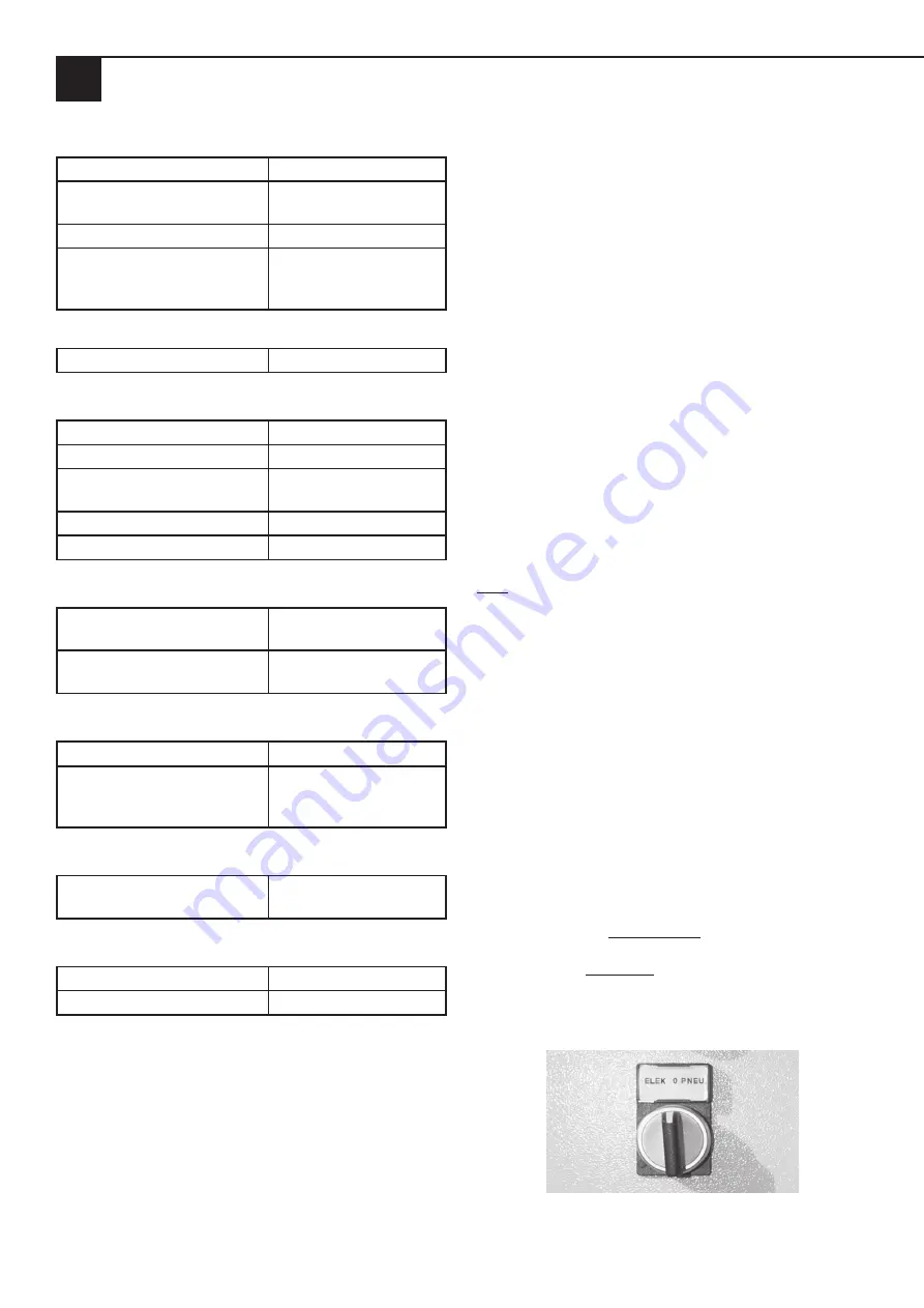
is controlled either pneumatically (via the air valve on the
spraying device – to do this, set the “ELEC 0 PNEU” switch
to “PNEU”), or electrically via a remote control cable laid
from the switching cabinet to the spraying device. Here, the
machine is controlled by an on/off switch. In this case, turn
the “ELEC 0 PNEU” switch to the left to “ELEC”.
Switch for electrical or pneumatic control of the machine.
Summary of Contents for inoCOMB Picco Power
Page 41: ...Page 41 EN Chapter 13 Systems 13 3 Circuit diagram for compressor...
Page 42: ...Page 42 EN Chapter 13 Systems 13 3 1 Circuit diagram for mixer motor safety switch...
Page 44: ...Page 44 EN Chapter 13 Systems 13 3 3 Circuit diagram for pump rotation speed...
Page 45: ...Page 45 EN Chapter 13 Systems 13 3 4 Switching cabinet subplate inside...
Page 46: ...Page 46 EN Chapter 13 Systems 13 3 5 Switching cabinet outside...


