Installation and Programming Manual
Installation
27
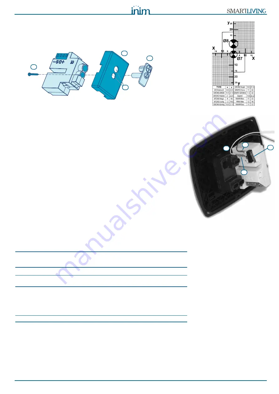
1. Ensure that the centre of the cover plate coincides with the crossing of the
axes x and y on the drill-pattern. In this way, the two drilling locations (1 x
7mm diameter and 1 x 8mm diameter) will be positioned precisely.
2. Using the screw [D], secure the reader components inside the cover plate.
3. Insert the cover plate (with the reader already assembled) into the light
switch box.
Dislodgement tamper
The nBy/X reader is not equipped with built-in dislodgement-tamper protection.
However, the following section describes how you can protect nBy/X reader
against this kind of tamper.
In order to comply with Italian certification (Level 2 - IMQ Security Systems), all
the system peripherals must be protected against tamper. Installation of a
microswitch will allow the reader to signal tamper events. To obtain this type of
protection, work carefully through the following steps.
1. Use a microswitch with at least two normally-open contacts [A]. The one
shown in figure 3 has 3 contacts: COM-NO-NC.
2. Configure one of the terminals as follows: Input; 24H; Description =
“Tamper reader x”; single balancing with 6K8
W
[resistance [B]; unlimited
alarm cycles. Assign the duly programmed terminal to at least one keypad
partition.
3. Using 2 wires, connect the microswitch to the 24H input terminal.
4. On the microswitch:
4.1. using one of the two wires, connect the common contact (COM) to the
GND terminal of the 24H terminal [C].
4.2. Connect the normally-open contact (NO) to one end of the 6k8
W
resistance [D] (the normally-open contact generates a short-circuit
between itself and the COM contact when the microswitch-lever is
compressed). Connect the other end of the resistance to the wire
which is connected to the 24h input terminal.
5. Install the microswitch as shown in the previous figure, so that the switch
lever is compressed. If an unauthorized attempt to dismantle the nBy/X
reader occurs, the lever will expand in order to open the contact which trig-
gers instant alarms on the 24H terminal.
Note
This wiring method can be applied in most situations, however, it is only a point of
reference. In order to ensure proper protection, you must always take in to account the
specific mechanical and electrical conditions of the device you are working on.
ATTENTION!
In order to avoid malfunction, it is advisable not to install nBy/X readers onto
metal plates.
3-2-6
Installing the Nexus
In order to allow this device to function properly, you must install it in a safe, dry
place which provides the best possible GSM reception.
ATTENTION!
Disable the SIM card PIN.
1. Ensure that the Nexus is not powered-up.
2. Insert the SIM card into its housing (refer to
Table 20: Nexus - description
of parts, E
).
3. Install the antenna and connect it to the respective input (refer to
Table
20: Nexus - description of parts, B
).
4. Connect the BUS to the terminal board (refer to
Table 20: Nexus - descrip-
tion of parts, A
).
C
A
D
B
D
A
C
B


