Installation and Programming Manual
Installation
29
3-3-1
Addressing the keypads
Work carefully through the following steps.
1. Put the control panel in “Maintenance” mode by inserting the respective
jumper (
Table 4: Control panels - description of parts, Q
).
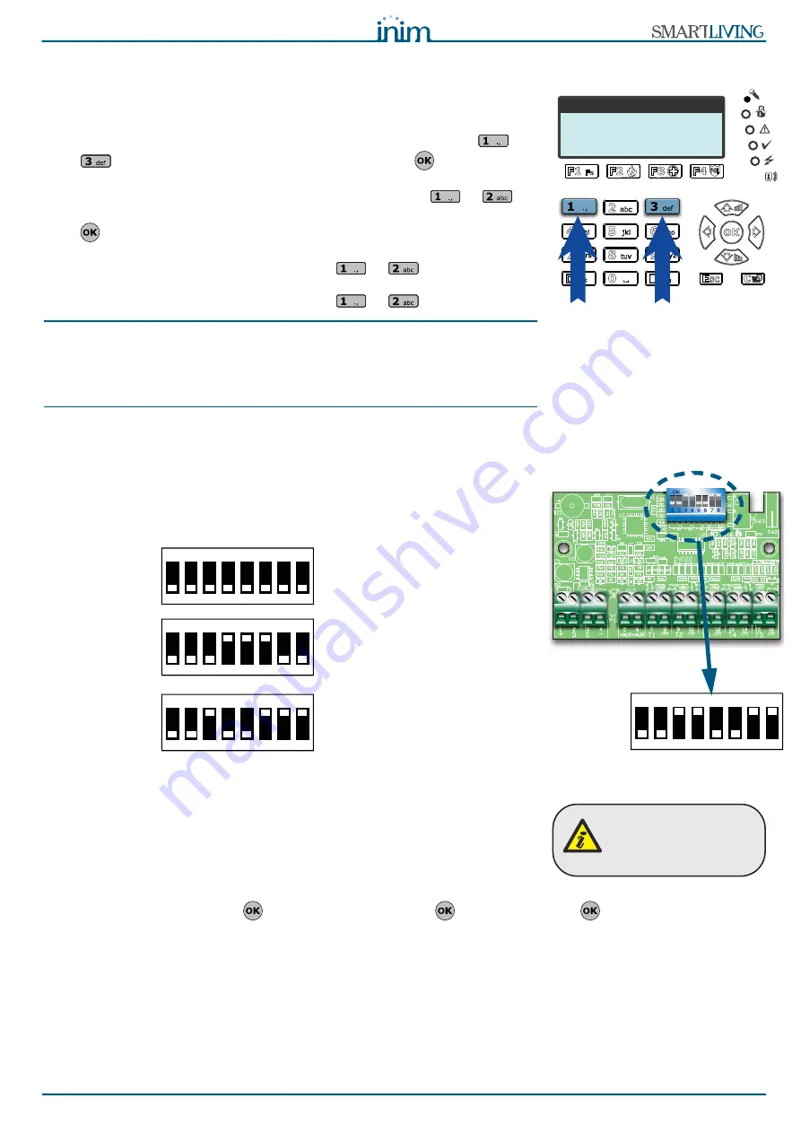
2. Using the keypad you wish to address, press and release keys
and
simultaneously; set the address then press
(if the keypad
firmware version is 1.02 or higher, go to point 5).
3. For JOY/MAX only: enable or disable the reader press keys
or
.
4. For JOY/MAX only: if the reader is enabled, assign the address and press
.
5. If the keypad firmware version is 1.02 or higher, enable or disable the dis-
lodgement tamper protection by pressing
or
.
6. If the keypad firmware version is 1.08 or higher, enable or disable the dis-
lodgement tamper protection by pressing
or
.
Note
For security reasons, if the address is not assigned within 30 minutes of accessing
“Maintenance” mode (SERV jumper inserted), the keypad will exit the programming phase
automatically.
If this occurs and you wish to restart the programming phase, remove and re-insert the
jumper.
The same procedure is necessary when you re-address the keypad.
3-3-2
Addressing FLEX5 expansions and the
Air2-BS100 transceiver
Using a small screwdriver or similar tool, set the expansion board address on the
8-segment DIP-Switch strip (
Table 17: Flex5 - Description of parts, C
). Each
segment can be set at “1” (On) or “0” (Off).
The figure shows some examples.
3-3-3
Addressing nBy readers
To assign addresses to the system readers, work carefully through the following
steps.
1. Put the control panel in “Maintenance” mode by inserting the respective
jumper (
Table 4: Control panels - description of parts, Q
).
2. Start the “Address Programming” phase using the software or from a key-
pad:
Type-in Code
(Installer PIN)
, PROGRAMMING Readers
, Prog. address
.
3. Each reader indicates its own address on its LEDs (refer to the Table in
paragraph
3-3 Addressing the peripherals
).
4. Hold a valid key in the vicinity of the reader. The reader will run through a
series of available reader-addresses (an address every 2 seconds). Remove
the key when the LEDs indicate the desired address.
5. The reader will hold the addressing phase for a further 10 seconds, in order to
allow you to change the address if necessary.
6. The reader will assign the selected address when the 10 second period
expires.
k e y p a d a d d r e s s
_ 1
M i n . 0 1
M a x . 3 0
ON
1 2 3 4
5 6 7 8
Position 1
Position 2
ON
1 2 3 4
5 6 7 8
ON
1 2 3 4
5 6 7 8
ON
1 2 3 4
5 6 7 8
Expansion n. 1
Expansion n.29
Expansion n.40
This procedure does
not apply to the built-in
readers of JOY/MAX
keypads.


