


Everest CORE - Product Manual |
Application Guide
INGENIA | 08/01/2019
25
•
Reduce voltage ripple in the DC bus to improve EMI ratings
•
Reduce voltage ripple in the DC bus to reduce power losses
•
Store excess of energy during regenerative braking.
The suggested solution does not target the regenerative braking issue, as an specific circuit is proposed to this
purpose below in this guide (see Shunt Braking Resistor Transistor chapter). Then, when it comes to reduce the DC
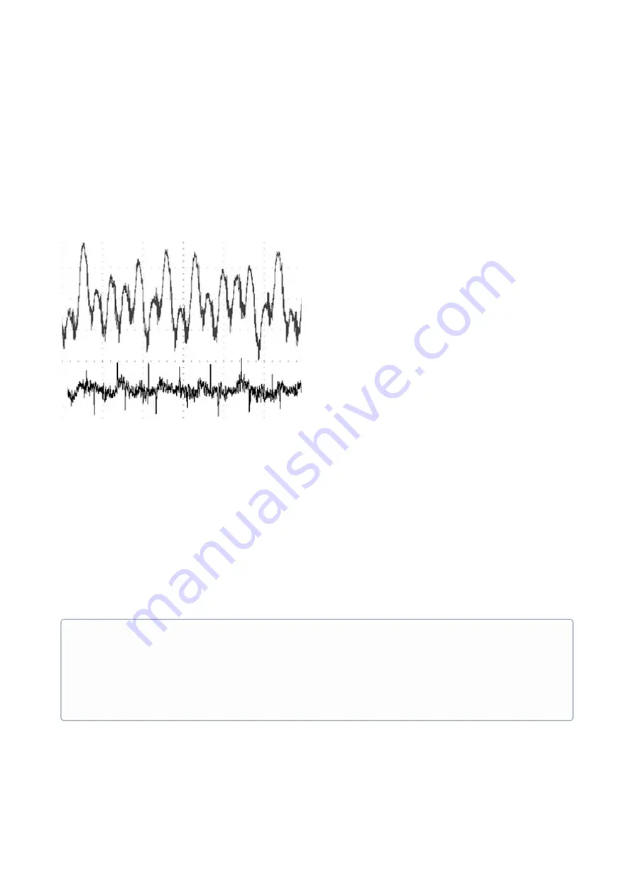
bus voltage ripple, it is interesting to distinguish between 2 phenomena causing it. In the image below this 2 types
of ripple are depicted. The top one has more amplitude, but edges are round and soft, so it mostly carries lower
frequency harmonic components. The bottom one has less amplitude, but has sharp edges of a great dV/dt, so it
carries higher frequency harmonics. Typically the 2 types of ripple will be seen at the same time over a saw-tooth
base shape, but the magnitude of each will typically depend on the amount of current delivered to the motor, and
its phase inductance.
High frequency ripple is more likely to increase when the Everest CORE is delivering high phase currents. This ripple
does not carry much overall energy, but requires capacitors capable of responding at high frequencies with low
ESR. Therefore, the best option here will be
ceramic capacitors
, which by nowadays will typically over-perform
tantalum, electrolytic or polymer capacitors. Although the minimum required ceramic capacity is already included
inside the Everest CORE, it is strongly suggested to add at least
30 µF ceramic capacity
externally as close as
possible to the Everest CORE, to get a reasonable performance in a mid-range application.
Low frequency ripple is more likely to increase when the Everest CORE is driving a low inductance motor, specially
when driving it at high currents. This ripple can get to carry a lot of energy, and therefore a larger capacity would be
required. Here, ceramic capacitors are still the best choice, but installing a large bank of ceramic capacity can be
space-consuming and very expensive, while electrolytic capacitors, specially
aluminium electrolytic capacitors
,
show much better ratios in capacity per volume at a lower cost. However, be aware that having electrolytic
capacitors in a commercial product might entail
serious drawbacks
: they can contain dangerous chemicals, they
can explode if mounted in reverse polarity, they could limit the temperature rating of the whole product, and they
would probably become the shortest lifetime component of the design (MTBF bottleneck).
Finally, it is advisable to include
sourge and ESD protection
in the power DC input to reinforce the immunity
ratings of the Everest CORE. A TVS could do the job for ESD protection, but might be insufficient in front of a sourge,
where suppression of large but very short power peaks is not as relevant as the response in front of a wide and long
Electrolytic capacitors
Ingenia recommends not to use electrolytic capacitors unless there is no other way to satisfy the
requirements of an application. In such case, select only the highest quality capacitors, with specs such as:
•
Temperature rating > 100 ºC
•
Low ESR / high ripple withstanding
•
Certified lifetime at high temperature (MTBF) > 6000 hours.
Also, always apply a over-dimension in the voltage rating of electrolytic capacitors of at least x1.3


