2 - 44
ACC (acceleration) [m/s
2
]
7) Connect the voltmeter to [INPUT Ch1 MONITOR] as it is. Record the measured
AC voltage.
8) Change the connection of [OUTPUT Ch1] to [INPUT Ch2] of the I/O UNIT. Also
change the input setting of K2 to Ch.2 from Ch.1. The input sensitivity of Ch.2 is
the same as Ch.1.
9) Operate the same procedure as 3)
~
7) and record the measured data.
10) These procedures are also needed to be operated for Ch.3 and Ch.4. When the
optional input channels are added, the input channels Ch1. ~ Ch8 of the expansion
board are also needed to be measured and recorded.
<
Charge input sensitivity test
>
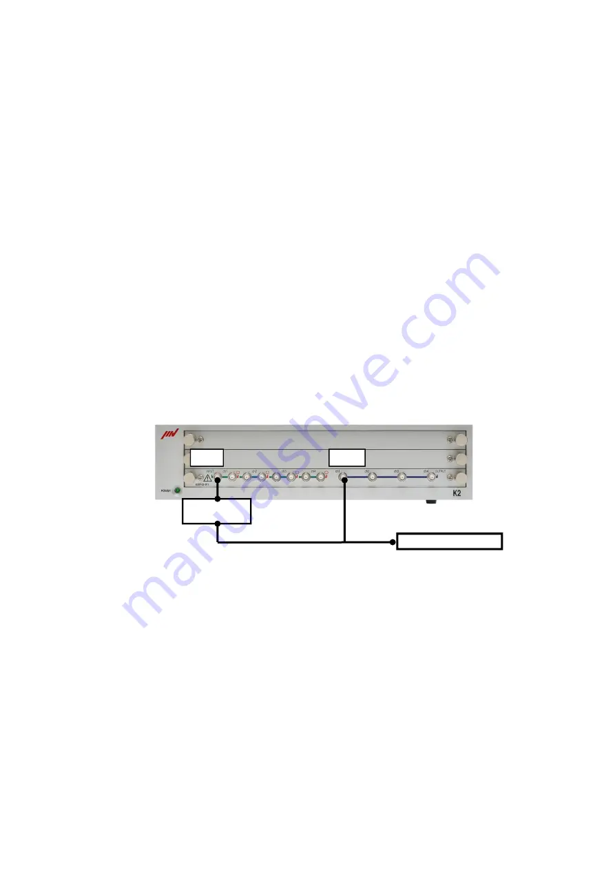
Connection of the instruments
Connect the equipment by the cables as in the same way as in the system of
<Voltage input sensitivity test / monitoring output test> above. Also connect [INPUT
Ch1] of the I/O input to the capacitor.
Operate the performance check
1) Record the capacitance of the used capacitor and calculate the input voltage by the
equation.
C : Capacitance [pF]
V : Input voltage [mVrms]
V = 1000 ÷ C × 353.5
Example) Input voltage 354.4mV is obtained when the capacitance of the used
capacitor is 997.4pF.
2) Select the manual operation.
Set conditions :
output [80Hz 500mV]
input type [Charge input (1mV/pC)]
input sensitivity for Ch.1 [5pC/(m/s
2
)]
Input
Output
Voltmeter
Capacitor
Summary of Contents for K2-CE
Page 4: ......
Page 34: ...2 6 Step 2 The initial screen of installation appears Press the button of Next...
Page 38: ...2 10 Step 2 The initial screen of installation appears Press the button of Next...
Page 49: ...2 21 Step 2 The initial screen of installation appears Press the button of Next...
Page 55: ...2 27 Step 3 The screen displaying the message of Uninstall or change a program appears...
Page 58: ...2 30 Step 3 The screen displaying the message of Uninstall or change a program appears...
Page 81: ......
Page 82: ......
Page 92: ...4 3 4 2 2 Exit from Application 1 K2 Launcher Press the button Close on the screen...
Page 107: ...4 18 Step 3 A graph of the page displayed currently appears in the display...
Page 110: ...4 21 Step 3 Additional graph appears on the currently displayed page...
Page 121: ...4 32 Step3 Press the Mark button to mark the cursor data displayed in the list...
Page 141: ...4 52 Step 2 Press Yes when a dialog of message for assuring appears...
Page 149: ...4 60 Step 5 Press the OK button...
Page 170: ...4 81 Step 9 Press OK after completing of the necessary settings...
Page 172: ...4 83 Report of testing result generated by Report Generator...
Page 196: ...6 12 Step 3 Select desired data file Some files can be selected at a time...
Page 201: ...6 17 Step 3 Select desired data file Some files can be selected at a time...
Page 212: ...7 6 7 2 2 Standards Mode Procedures Step 1 Press the button of Standards...
Page 217: ...7 11 7 2 3 Test files mode Procedures Step 1 Press the button of Test files...


