6.
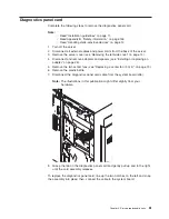
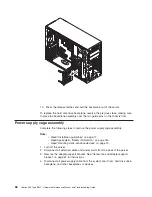
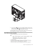
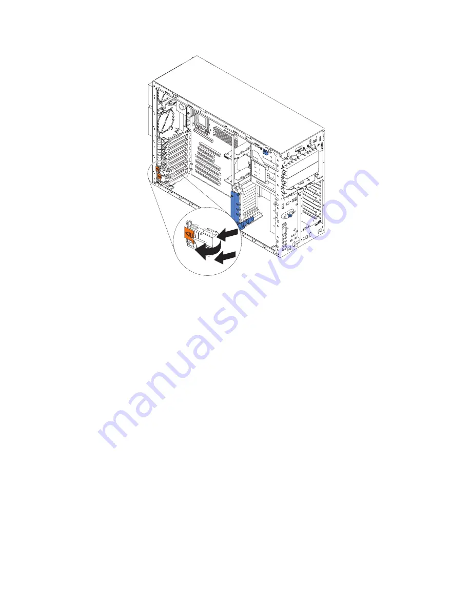
Press
the
two
tabs
on
the
switch
card
and
remove
it
from
the
chassis.
Note:
It
might
be
easier
to
remove
this
component
if
the
server
is
placed
on
its
side.
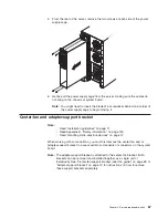
To
install
the
switch
card
assembly,
line
up
the
two
tabs
with
the
notches
on
the
chassis
and
snap
the
assembly
into
place;
then,
connect
the
cable
to
the
system
board.
Chapter
4.
Service
replaceable
units
75
Summary of Contents for xSeries 236 8841
Page 1: ...xSeries 236 Type 8841 Hardware Maintenance Manual and Troubleshooting Guide...
Page 2: ......
Page 3: ...xSeries 236 Type 8841 Hardware Maintenance Manual and Troubleshooting Guide...
Page 20: ...10 xSeries 236 Type 8841 Hardware Maintenance Manual and Troubleshooting Guide...
Page 96: ...86 xSeries 236 Type 8841 Hardware Maintenance Manual and Troubleshooting Guide...
Page 152: ...142 xSeries 236 Type 8841 Hardware Maintenance Manual and Troubleshooting Guide...
Page 160: ...150 xSeries 236 Type 8841 Hardware Maintenance Manual and Troubleshooting Guide...
Page 173: ...Appendix B Safety information 163...
Page 174: ...164 xSeries 236 Type 8841 Hardware Maintenance Manual and Troubleshooting Guide...
Page 175: ...Appendix B Safety information 165...
Page 176: ...166 xSeries 236 Type 8841 Hardware Maintenance Manual and Troubleshooting Guide...
Page 177: ...Appendix B Safety information 167...
Page 178: ...168 xSeries 236 Type 8841 Hardware Maintenance Manual and Troubleshooting Guide...
Page 179: ...Appendix B Safety information 169...
Page 189: ...Appendix B Safety information 179...
Page 190: ...180 xSeries 236 Type 8841 Hardware Maintenance Manual and Troubleshooting Guide...
Page 191: ...Appendix B Safety information 181...
Page 192: ...182 xSeries 236 Type 8841 Hardware Maintenance Manual and Troubleshooting Guide...
Page 196: ...186 xSeries 236 Type 8841 Hardware Maintenance Manual and Troubleshooting Guide...
Page 208: ...198 xSeries 236 Type 8841 Hardware Maintenance Manual and Troubleshooting Guide...
Page 209: ......
Page 210: ...Part Number 25K8114 1P P N 25K8114...

