v
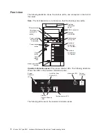
System
power-on
LED:
When
this
LED
is
lit
and
not
flashing,
it
indicates
that
the
server
is
turned
on.
When
this
LED
is
flashing,
it
indicates
that
the
server
is
turned
off
and
still
connected
to
an
ac
power
source.
When
this
LED
is
off,
it
indicates
that
ac
power
is
not
present,
or
the
power
supply
or
the
LED
itself
has
failed.
A
power
LED
is
also
on
the
rear
of
the
server.
v
OK
LED:
This
green
LED
is
lit
only
when
the
Front
Panel
LED
test
is
performed
by
the
Enhanced
Diagnostics.
v
Hard
disk
drive
activity
LED:
When
this
green
LED
is
flashing
rapidly
it
indicates
that
there
is
activity
on
a
hard
disk
drive.
v
System-information
LED:
When
this
amber
LED
is
on,
the
server
power
supplies
are
nonredundant,
or
some
other
noncritical
event
has
occurred.
The
event
is
recorded
in
the
error
log.
Check
the
light
path
diagnostic
panel
for
more
information
(see
the
“Light
path
diagnostics”
on
page
93.
v
System-error
LED:
When
this
amber
LED
is
lit
it
indicates
that
a
system
error
has
occurred.
Use
the
diagnostic
LED
panel
and
the
system
service
label
on
the
inside
of
the
left-side
cover
to
further
isolate
the
error.
See
“Light
path
diagnostics”
on
page
93
for
additional
information.
v
System
locator
LED:
Use
this
LED
to
visually
locate
the
server
among
other
servers.
You
can
use
IBM
Director
to
light
this
LED
remotely.
v
Ethernet
transmit/receive
activity
LED
(Tx/Rx
1
or
Tx/Rx
2):
When
these
two
green
LEDs
are
lit
they
indicate
that
there
is
activity
between
the
server
and
the
network.
USB
3
connector:
Connect
a
USB
device
to
this
connector.
Diskette-eject
button:
Press
this
button
to
release
a
diskette
from
the
diskette
drive.
Diskette
drive
activity
LED:
When
this
LED
is
lit,
it
indicates
that
the
diskette
drive
is
in
use.
Hard
disk
drive
activity
LED:
When
this
LED
is
flashing,
it
indicates
that
the
associated
hard
disk
drive
is
in
use.
Hard
disk
drive
status
LED:
When
this
LED
is
lit,
it
indicates
that
the
associated
hard
disk
drive
has
failed.
If
an
optional
RAID
adapter
is
installed
in
the
server
and
the
LED
flashes
slowly
(one
flash
per
second),
the
drive
is
being
rebuilt.
If
the
LED
flashes
rapidly
(three
flashes
per
second),
the
controller
is
identifying
the
drive.
Reset
button:
Press
this
button
to
reset
the
server
and
run
the
power-on
self-test
(POST).
You
might
have
to
use
a
pen
or
the
end
of
a
straightened
paper
clip
to
press
the
button.
Power-control
button:
Press
this
button
to
turn
the
server
on
and
off
manually.
A
power-control-button
shield
comes
with
the
server.
You
can
install
this
disk-shaped
shield
to
prevent
the
server
from
being
turned
off
accidentally.
Power-control-button
shield:
You
can
install
this
circular
disk
over
the
power-control
button
to
prevent
the
server
from
being
turned
off
accidently.
CD-ROM
drive
activity
LED:
When
this
LED
is
lit,
it
indicates
that
the
CD-ROM
drive
is
in
use.
CD-eject
button:
Press
this
button
to
release
a
CD
from
the
CD-ROM
drive.
Chapter
1.
General
information
5
Summary of Contents for xSeries 236 8841
Page 1: ...xSeries 236 Type 8841 Hardware Maintenance Manual and Troubleshooting Guide...
Page 2: ......
Page 3: ...xSeries 236 Type 8841 Hardware Maintenance Manual and Troubleshooting Guide...
Page 20: ...10 xSeries 236 Type 8841 Hardware Maintenance Manual and Troubleshooting Guide...
Page 96: ...86 xSeries 236 Type 8841 Hardware Maintenance Manual and Troubleshooting Guide...
Page 152: ...142 xSeries 236 Type 8841 Hardware Maintenance Manual and Troubleshooting Guide...
Page 160: ...150 xSeries 236 Type 8841 Hardware Maintenance Manual and Troubleshooting Guide...
Page 173: ...Appendix B Safety information 163...
Page 174: ...164 xSeries 236 Type 8841 Hardware Maintenance Manual and Troubleshooting Guide...
Page 175: ...Appendix B Safety information 165...
Page 176: ...166 xSeries 236 Type 8841 Hardware Maintenance Manual and Troubleshooting Guide...
Page 177: ...Appendix B Safety information 167...
Page 178: ...168 xSeries 236 Type 8841 Hardware Maintenance Manual and Troubleshooting Guide...
Page 179: ...Appendix B Safety information 169...
Page 189: ...Appendix B Safety information 179...
Page 190: ...180 xSeries 236 Type 8841 Hardware Maintenance Manual and Troubleshooting Guide...
Page 191: ...Appendix B Safety information 181...
Page 192: ...182 xSeries 236 Type 8841 Hardware Maintenance Manual and Troubleshooting Guide...
Page 196: ...186 xSeries 236 Type 8841 Hardware Maintenance Manual and Troubleshooting Guide...
Page 208: ...198 xSeries 236 Type 8841 Hardware Maintenance Manual and Troubleshooting Guide...
Page 209: ......
Page 210: ...Part Number 25K8114 1P P N 25K8114...


