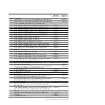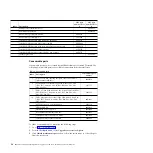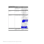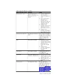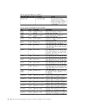
Table 6. System board diagnostic LED information (continued)
LED
Color
LED name
Description
DLLUP20
Green
Ethernet 2-0 link
This LED lights when port 0 on LOM
controller 2 is connected to the network.
DLLUP21
Green
Ethernet 2-1 link
This LED lights when port 1 on LOM
controller 2 is connected to the network.
DLPWROK1
Green
Ethernet 1 power OK
This LED lights when power to LOM
controller 1 is on and working properly.
DLPWROK2
Green
Ethernet 2 power OK
This LED lights when power to LOM
controller 2 is on and working properly.
DPWRFAULT
Yellow
Power fault
This LED lights when there is an
overcurrent fault on one of the 12 V
power rails.
DS6
Yellow
ETE standby power
disable
This LED lights when standby power on
the ETE sidecar is disabled.
DS862
Green
RTMM heartbeat
This LED lights when there is activity
on the RTMM.
DS913
Green
IMM heartbeat
This LED lights when there is activity
on the IMM2.
DSL01
Yellow
SAS back plane 1 error The IMM lights this LED and the fault
LED when there is a problem with SAS
backplane 1.
DSL02
Yellow
SAS Back Plane 2 error The IMM2 light this LED and the fault
LED when there is a problem with SAS
backplane 2.
DSAS_LF10
Yellow
SAS 1-0 link failure
The IMM lights this LED and the fault
LED when there is a fault with the link
between the SAS controller and SAS
Port 0 on SAS backplane 1.
DSAS_LF11
Yellow
SAS 1-1 link failure
The IMM lights this LED and the fault
LED when there is a fault with the link
between the SAS controller and SAS
Port 1 on SAS backplane 1.
DSAS_LF20
Yellow
SAS 2-0 link failure
The IMM2 lights this LED when there is
a fault with the link between the SAS
controller and SAS port 0 on SAS
backplane 2.
DSAS_LF21
Yellow
SAS 2-1 link failure
The IMM2 lights this LED when there is
a fault with the link between the SAS
controller and SAS port 1 on SAS
backplane 2.
DSERROR
Yellow
SAS error
This LED lights when there is a problem
with the LSI2004 SAS controller.
DSHB
Green
SAS heartbeat
This LED lights when there is activity
on the LSI2004 SAS controller.
IMM event log
Use this information as an overview of the IMM event log.
The integrated management module II (IMM2) consolidates the
system-management processor functionality, video controller, and remote presence
Chapter 6. Troubleshooting
63
Summary of Contents for Flex System x440 Compute Node
Page 1: ...IBM Flex System x440 Compute Node Types 7917 and 2584 Installation and Service Guide ...
Page 2: ......
Page 3: ...IBM Flex System x440 Compute Node Types 7917 and 2584 Installation and Service Guide ...
Page 34: ...22 IBM Flex System x440 Compute Node Types 7917 and 2584 Installation and Service Guide ...
Page 50: ...38 IBM Flex System x440 Compute Node Types 7917 and 2584 Installation and Service Guide ...
Page 68: ...56 IBM Flex System x440 Compute Node Types 7917 and 2584 Installation and Service Guide ...
Page 498: ...486 IBM Flex System x440 Compute Node Types 7917 and 2584 Installation and Service Guide ...
Page 570: ...558 IBM Flex System x440 Compute Node Types 7917 and 2584 Installation and Service Guide ...
Page 578: ...566 IBM Flex System x440 Compute Node Types 7917 and 2584 Installation and Service Guide ...
Page 583: ......
Page 584: ... Part Number 81Y1144 Printed in USA 1P P N 81Y1144 ...

