Note:
The lever rotates upward or downward 90°, depending on whether
the power supply and fan unit you are removing is in the right or left
power supply and fan unit bay.
c. Repeat steps 7a on page 120 and 7b on page 120 for the other power
supply and fan unit.
8. Remove the Telco bezel if it is installed. See “Removing and replacing a bezel”
on page 90 for instructions.
9. Label the Enhanced Disk Drive Module (E-DDM) CRUs so you know their
physical location in the midplane.
10. Remove the E-DDM CRUs and any blank drive CRUs if the storage expansion
enclosure has them. See “Replacing hot-swap hard disk drives” on page 95 for
instructions. Place E-DDMs on ESD protected surface.
Attention:
Do not stack E-DDM CRUs on top of each other. Protect the
E-DDM CRUs from vibrations or sudden shocks.
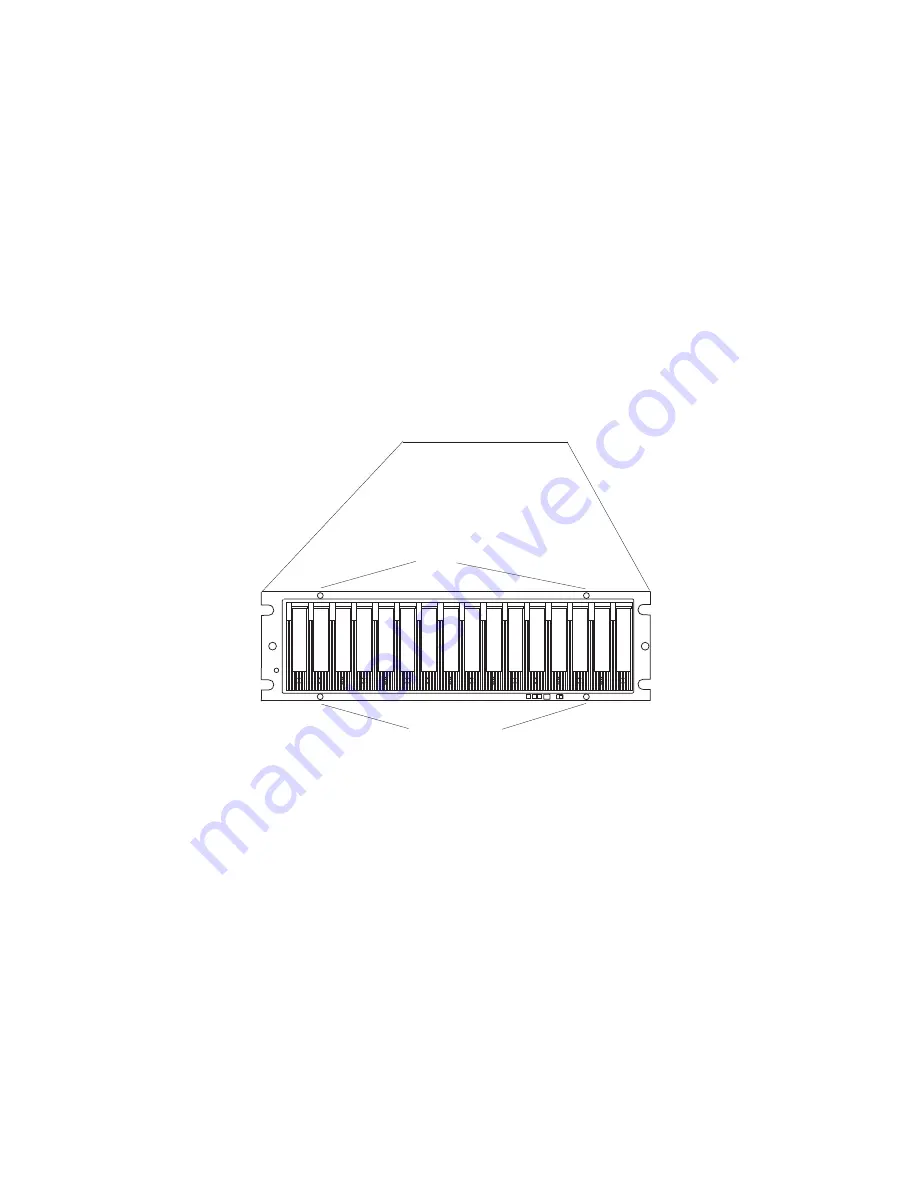
11. Use a #1 Phillips screwdriver to loosen the four front cage frame screws on the
midplane, as shown in Figure 58.
Front cage frame screws
810midpl
Front cage frame screws
Figure
58.
Front
cage
frame
screw
locations
12. On the back of the EXP810, remove the four Phillips screws (two screws on
each side) that hold the sides of the EXP810 chassis to the sides of the rails.
13. On the front of the EXP810, remove the four M5 screws (two screws on each
side) on the EXP810 chassis that hold the EXP810 to the rails.
Attention:
The unit must be removed from the rack and placed on a level
ESD protected surface before servicing it.
14. Pull the chassis outward from the front of the rack and remove from the rack.
Place it on a level surface. Look for a row of three Phillips screws on top of the
chassis and a row of four Phillips screws on the bottom of the chassis, as
shown in Figure 59 on page 122. Remove the seven Phillips screws using the
#1 Phillips screwdriver. Save these screws.
Chapter 5. Installing and replacing components
121
Summary of Contents for DS4000 EXP810
Page 2: ......
Page 67: ...ds470067 Figure 20 Installing a bezel Chapter 2 Installing the EXP810 39...
Page 229: ......
Page 230: ...Printed in USA GC26 7798 09...


