


32
5. Outline of CC-Link
5.1 Data communication
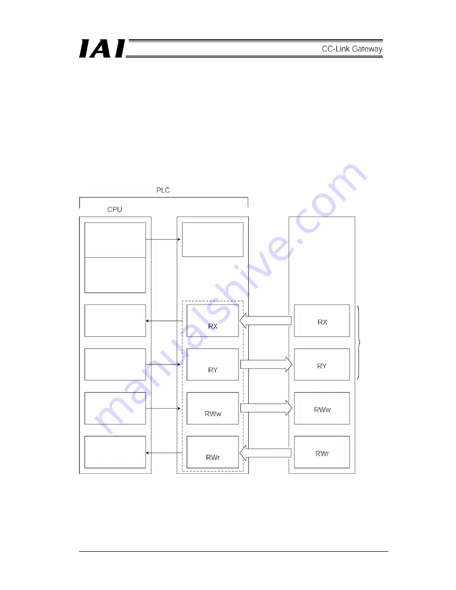
A scheme for basic data communication of the CC-Link is as shown in the following diagram.
For slave to master station of the PLC, there are remote I/O stations which handle bit information only and
remote device stations which handle bit information and word information (numeric data).
The master station has a buffer memory which is divided into remote input RX, remote output RY and remote
register RWw/RWr. The remote input and output RX/RY handle bit information, and the remote register
RWw/RWr handle word information (numeric data). Data is automatically communicated between the master
station and slave station via this buffer memory regardless of the CPU for the PLC.
The CPU uses the buffer memory in the master station and the CPU internal device (such as X.Y.M.D.W) to
communicate data.
Network
parameter
Automatic
refresh
parameter
CPU device
corresponded to RX
(such as X.M)
CPU device
corresponded to RY
(such as Y.M)
CPU device
corresponded to
RWw (such as D.W)
CPU device
corresponded to RWr
(such as D.W)
Network
parameter
Master station
Buffer memory
Remote input
Remote output
Remote register
Remote register
Link scan
Link scan
Link scan
Link scan
Remote input
(bit signal)
Remote output
(bit signal)
Remote register
(numeric data)
Remote register
(numeric data)
Slave
Remote device station
The remote I/O
stations have
these only.
Summary of Contents for RCM-GW-CC
Page 1: ...IAI America Inc CC Link RCM GW CC Gateway Unit Operation ManualFirst Edition...
Page 4: ......
Page 10: ...6 1 5 How to identify model RCM GW CC Basic model For CC Link Gateway unit...
Page 12: ...8 2 2 External dimension drawing Mounting dimension...
Page 78: ...74...
Page 82: ...78 Position data measurement value Present position 1 2 3 4 4 5 6 7...
Page 84: ...80 Speed acceleration and deceleration set value Actuator speed Speed n2 Speed n3 1 2 3...
Page 88: ...84 Command position No Completion position No 1 2 3 4 5 6...
Page 91: ...87...
Page 93: ...89...
Page 125: ...121 No 3 Axis 1 pause No 3 Axis 1 pause lamp No 3 Axis 1 STP...
Page 130: ...126...
Page 131: ......


