12
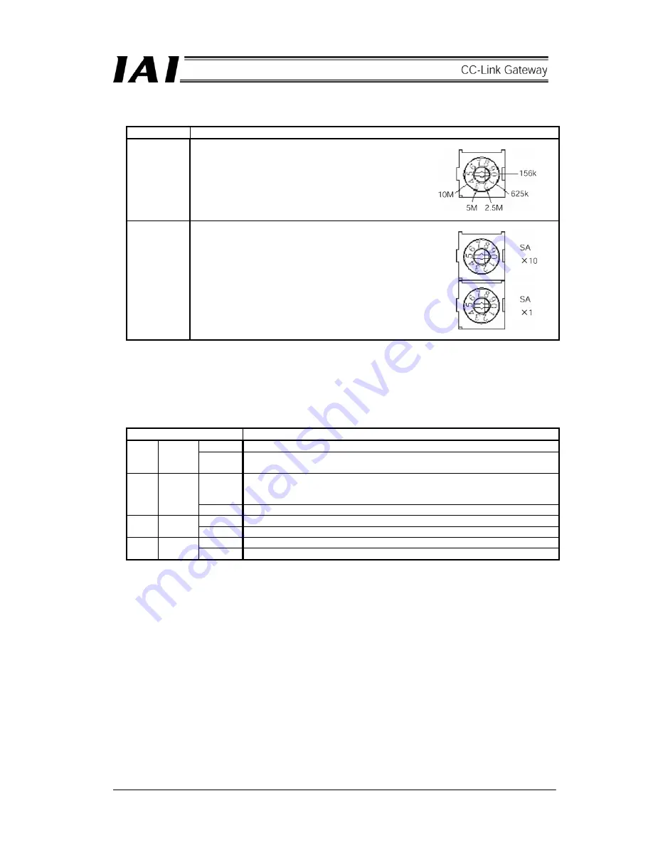
[7] CC-Link setting switch
Switch Description
BR
[Baud rate setting switch]
This switch sets the communication rate.
Setting of 5 or higher is prohibited.
SA
×
10
SA
×
1
[Station No. setting switch]
This switch sets with decimal two digits, however,
effective setting is from 1 to 64.
Positions of SA
×
10
・・・
10 are set.
Positions of SA
×
1
・・・
1 are set.
(Example) When setting station No. 12,
set 1 to SA
×
10, and
set 2 to SA
×
1.
* When changing the setting with the power on, the ERRLED of the next [8] is lit.
[8] CC-Link communication status LED
Operating status of the CC-Link gateway and network status can be checked by the four LEDs.
Indicating status
Description
Lit
Normal operation (Lit by starting communication)
RUN Green
Unlit
Does not participate in network or time out status (Communication is
interrupted for a certain time or longer)
Lit
Reception data to self station is abnormal (CRC error).
Setting of baud rate setting switch or station No. setting switch is changed
during communication.
ERR Red
Unlit Normal
Lit
Data is being received
RD Green
Unlit
No reception data
Flashing Data is being transmitted
SD Green
Unlit
No transmission data
Summary of Contents for RCM-GW-CC
Page 1: ...IAI America Inc CC Link RCM GW CC Gateway Unit Operation ManualFirst Edition...
Page 4: ......
Page 10: ...6 1 5 How to identify model RCM GW CC Basic model For CC Link Gateway unit...
Page 12: ...8 2 2 External dimension drawing Mounting dimension...
Page 78: ...74...
Page 82: ...78 Position data measurement value Present position 1 2 3 4 4 5 6 7...
Page 84: ...80 Speed acceleration and deceleration set value Actuator speed Speed n2 Speed n3 1 2 3...
Page 88: ...84 Command position No Completion position No 1 2 3 4 5 6...
Page 91: ...87...
Page 93: ...89...
Page 125: ...121 No 3 Axis 1 pause No 3 Axis 1 pause lamp No 3 Axis 1 STP...
Page 130: ...126...
Page 131: ......


