17
4. Wiring
4.1 Overall Configuration
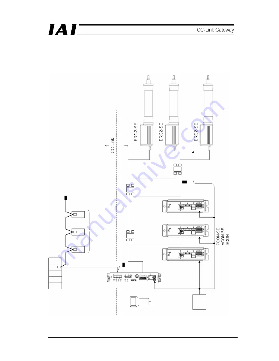
The following diagram shows an example of configuration to build a CC-Link by using a gateway unit.
Host system (PLC master st
ation)
Te
rminal resist
or
Slave st
atio
n
Gateway unit
Teachi
ng b
ox
Te
rminal
resistor
4-directi
on j
unc
tion
SIO communication n
etwork
Te
rminal resist
or
24V
power
supply
Summary of Contents for RCM-GW-CC
Page 1: ...IAI America Inc CC Link RCM GW CC Gateway Unit Operation ManualFirst Edition...
Page 4: ......
Page 10: ...6 1 5 How to identify model RCM GW CC Basic model For CC Link Gateway unit...
Page 12: ...8 2 2 External dimension drawing Mounting dimension...
Page 78: ...74...
Page 82: ...78 Position data measurement value Present position 1 2 3 4 4 5 6 7...
Page 84: ...80 Speed acceleration and deceleration set value Actuator speed Speed n2 Speed n3 1 2 3...
Page 88: ...84 Command position No Completion position No 1 2 3 4 5 6...
Page 91: ...87...
Page 93: ...89...
Page 125: ...121 No 3 Axis 1 pause No 3 Axis 1 pause lamp No 3 Axis 1 STP...
Page 130: ...126...
Page 131: ......


