22
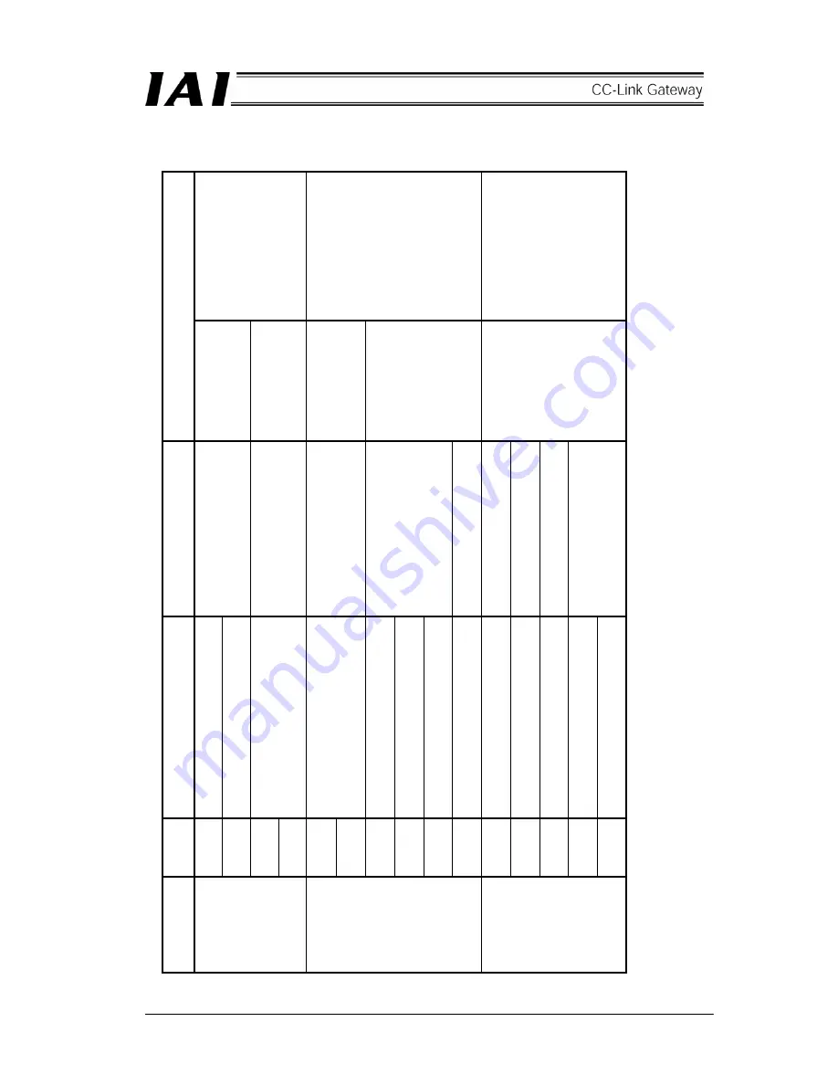
(3) Specification of input and output signal and wiring material
Conn
ectin
g plu
g is
st
andar
d att
achment.
MC1.5/6-ST
3
・
81
(PHOENIX CONT
ACT)
Conn
ectin
g plu
g is
st
andar
d att
achment.
MC1.5/4-ST
3
・
5
(PHOENIX CONT
ACT)
T
he gatew
ay u
nit
incorp
orates a
terminal
resistor
, therefore,
conn
ect the terminal
resistor to the end of the
SIO communication.
Conn
ectin
g plu
g is
st
andar
d att
achment.
It is necessary to connect
a terminal res
is
tor to both
ends of the CC
-Link
system (betwe
en DA
and
DB), therefore,
check the
Operatio
n Man
ual for the
master side (P
LC).
Conn
ector an
d
applic
ab
le el
e
ctric wire
0.8 – 1.3mm
2
A
W
G 18 – 16
0.08 – 1.5mm
2
A
W
G 28 - 16
0.08 – 1.5mm
2
A
W
G 28 - 16
T
w
o-p
aired twist
shiel
de
d cabl
e
(A
W
G
22)
Recomme
nd
ed
bran
d: T
aiyo
El
ectric
W
ire & Cable
HK-SB/202
76 XL
2P
×
A
W
G22
CC-Li
nk V
er
. 1.10
supp
orting
dedic
ated ca
bl
e
(Such as
F
A
NC-SBH,
F
A
NC-SB)
S
pecificati
on
24V DC
±
10
%
Consum
in
g
cur
rent 30
0mA
max.
Allow
abl
e lo
a
d volt
ag
e: 30
V
DC
Allow
abl
e lo
ad
current: 1A
No volt
a
ge (dr
y) cont
act inp
u
t
load: 2
4V DC
7mA
Set GND (grou
nd) lev
el to tha
t
of controller o
r ERC actuator
to be conn
ecte
d.
Internal
ly conn
ected to frame.
Internal
ly conn
ected.
Conte
nt
s
Gateway po
we
r supply
P
osit
ive
side of 24V D
C
Gateway po
we
r supply
N
eg
ative
side of 24V D
C
Teachi
ng b
ox e
m
ergency sto
p
signa
l outp
ut
External p
ort switchin
g in
put
SIO communication li
ne
A
SIO communication li
ne B
Ground
F
rame grou
nd
CC-Li
nk comm
unicati
on l
ine
A
CC-Li
nk comm
unicati
on l
ine B
CC-Li
nk comm
unicati
on gr
ou
nd lin
e
Shield
F
rame grou
nd
*
T
he gatew
ay u
nit is provid
ed
with the fo
llowi
ng on
e termina
l resistor respe
ctively
. Since the termin
al res
istor dep
ends
on th
e
CC-Li
nk cabl
e to be used, us
e a re
sistor suitable for the ca
ble.
Cabl
e F
A
NC-SBH
(CC-Li
nk
ded
ic
ated
hi
gh-p
erfo
rmance
ca
ble)
130
Ω
, 1/2W
Cabl
e F
A
NC-SB
(CC-Li
nk
ded
ic
ated
cab
le)
1
10
Ω
, 1/2W
Symbol
24V
N
S1
S2
POR
T
IN
POR
T
N
SDA
SDB
GND
FG
DA
DB
DG
SLD
FG
Power supply
input co
nnect
o
r
SIO
communic
atio
n
conn
ector
CC-Li
nk
communic
atio
n
conn
ector
Summary of Contents for RCM-GW-CC
Page 1: ...IAI America Inc CC Link RCM GW CC Gateway Unit Operation ManualFirst Edition...
Page 4: ......
Page 10: ...6 1 5 How to identify model RCM GW CC Basic model For CC Link Gateway unit...
Page 12: ...8 2 2 External dimension drawing Mounting dimension...
Page 78: ...74...
Page 82: ...78 Position data measurement value Present position 1 2 3 4 4 5 6 7...
Page 84: ...80 Speed acceleration and deceleration set value Actuator speed Speed n2 Speed n3 1 2 3...
Page 88: ...84 Command position No Completion position No 1 2 3 4 5 6...
Page 91: ...87...
Page 93: ...89...
Page 125: ...121 No 3 Axis 1 pause No 3 Axis 1 pause lamp No 3 Axis 1 STP...
Page 130: ...126...
Page 131: ......


