background image


BOLTSCOPE PRO

 - Bolt Tension Monitor 

87 

Chapter 9  Temperature Compensation 

9.1 Purpose 

The temperature of a fastener affects the overall physical length, as well as the 
velocity of a fastener.  As the temperature of a fastener increases, the ultrasonic 
length increases at a rate greater than the physical change in length.  If the user 
intends to measure the same fastener at different time intervals over the service 
life of the bolt, temperature compensation is very important to produce accurate 
results.  However, if a fastener will only be measured once, never to be 
measured again, temperature compensation is not needed, as long as the 
reference length and elongation are measured at the same temperature and 
time. 

The thermal expansion of the fastener and the ultrasonic change in velocity as a 
result of temperature are two separate effects.  However, for the purpose of the 

BOLTSCOPE PRO

, they are combined in a single factor known as the 

Temperature Coefficient (Tc).  The sections that follow outline the procedures for 
selecting and using the temperature compensation mode with the accessory 
temperature sensor. 

9.2 Manual Mode 

The manual mode option relies on the user to enter in the current temperature 
before measuring.  This is useful to those users that do not require temperature 
compensation, or have an external temperature device measuring the 
temperature. 

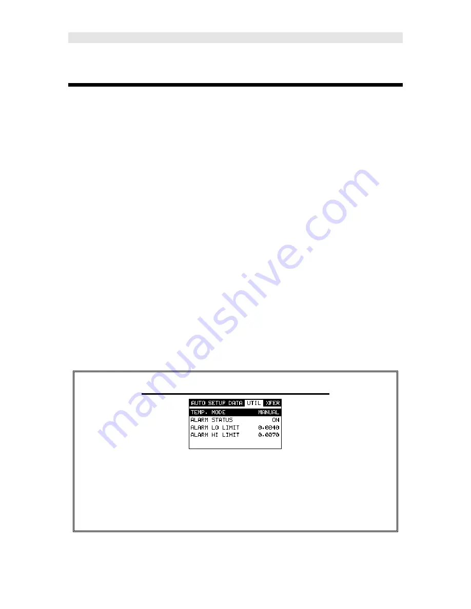
Selecting Manual Temperature Mode 


1) Press the 

MENU

 key once to activate the menu items tab.  Press the 

MENU

 key multiple times to tab right, and the 

ESC

 key multiple times to 

tab left, until the 

UTIL 

menu is highlighted and displaying the submenu 

items. 

Summary of Contents for BoltScope Pro

Page 1: ...B BO OL LT TS SC CO OP PE E P PR RO O B BO OL LT T T TE EN NS SI IO ON N M MO ON NI IT TO OR R OPERATING MANUAL P N P 189 0003 Rev 2 12 March 2012...

Page 2: ......

Page 3: ...ONNECTOR REFERENCE 20 4 1 MENU KEY OPERATION SUB MENUS 20 4 2 CAL MENU 22 4 3 MATL MATERIAL MENU 22 4 4 GEOM GEOMETRY MENU 23 4 5 DISP DISPLAY MENU 24 4 6 TUNE MENU 24 4 7 AUTO MENU 25 4 8 SETUP MENU...

Page 4: ...CALIBRATION 95 10 4 TEMPERATURE FACTOR CALIBRATION 98 CHAPTER 11 LOAD MEASUREMENT 102 11 1 CALCULATING A LOAD FACTOR 102 11 2 CALIBRATING A LOAD FACTOR FIELD CALIBRATION 105 11 3 PERFORMING A FIELD CA...

Page 5: ...169 14 6 EDITING A GROUP 170 14 7 CHANGING THE ACTIVE GROUP OPEN 173 CHAPTER 15 SETUPS CREATE STORE EDIT RECALL 175 15 1 INTRODUCTION TO SETUPS 175 15 2 OPENING A SETUP 175 15 3 SAVING A SETUP 177 15...

Page 6: ......

Page 7: ...ropriately or subject to unauthorized repair by the purchaser http www hydratight com 1 2 Safety Using the BOLTSCOPE PRO while standing in water or in a wet environment can result in serious electric...

Page 8: ...As a new user careful consideration of this entire manual is highly recommended 2 2 If you re new to fastener measurement Assuming you are familiar with ultrasonics but unfamiliar with fastener measu...

Page 9: ...he transducer cable to the transducer and plug the lemo connector into the gauge 3 If a temperature sensor is being used connect the sensor to the BOLTSCOPE PRO 3 3 Setting up the BOLTSCOPE PRO Please...

Page 10: ...ighlighted and displaying the submenu items 3 Use the UP and DOWN arrow keys to scroll through the sub menu items until OPEN is highlighted 4 Press the ENTER key to display the list of setups 5 Press...

Page 11: ...the MATL menu is highlighted and displaying the submenu items 2 Use the UP and DOWN arrow keys to scroll through the sub menu items until UNITS is highlighted 3 Press the LEFT and RIGHT arrow keys to...

Page 12: ...e UP and DOWN arrow keys to scroll through the sub menu items until TYPE is highlighted 2 Press the ENTER key to display the list material types 3 Press the UP and DOWN arrow keys to scroll through th...

Page 13: ...the UP and DOWN arrow keys to scroll through the sub menu items until NEW is highlighted 3 Press the ENTER key to display the New Group Edit Box 4 Use the UP and DOWN arrow keys to scroll through the...

Page 14: ...eted 10 Press the OK key to save the Group Name and return to the Group List Items menu or ESC to cancel entering the Group Name Creating a Group Note 1 Use the UP and DOWN arrow keys to scroll throug...

Page 15: ...key to save the Group Note and return to the Group List Items menu or ESC to cancel entering the Group Note Selecting the Number of Bolts in the Group Note A group can contain up to 250 bolts There mu...

Page 16: ...Edit Box and re enter the NUM BOLTS 8 Press the OK key to save the NUM BOLTS and return to the Group List Items menu or ESC to cancel entering the NUM BOLTS Selecting the Number of Readings Per Bolt...

Page 17: ...y the Digits Edit Box and re enter the NUM READS 8 Press the OK key to save the NUM READS and return to the Group List Items menu or ESC to cancel entering the NUM READS If there s not enough memory a...

Page 18: ...TART BOLT NUM value is correctly displayed 6 Press the OK key to save the START BOLT NUM and return to the Group List Items menu or ESC to cancel entering the START BOLT NUM Note If a value is enter t...

Page 19: ...tion to advance the cursor after storing a reading 1 Use the UP and DOWN arrow keys to scroll through the new Group List Items until INCR DIR is highlighted 2 Use the LEFT RIGHT arrow keys to toggle t...

Page 20: ...p setup and return to the DATA menu 4 Press the MEAS key to return to the measurement screen to begin measuring reference lengths 3 5 Setting the Approximate Length In order to utilize the AUTO SET fe...

Page 21: ...key to display the Digits Edit Box 3 Press the UP and DOWN arrow keys to scroll the highlighted value 4 Press the LEFT and RIGHT arrow keys to scroll the digit locations 5 Repeat steps 3 4 until the A...

Page 22: ...he UP and DOWN arrow keys to scroll the highlighted value 5 Press the LEFT and RIGHT arrow keys to scroll the digit locations 6 Repeat steps 4 5 until the Approx Len value is correctly displayed 7 Pre...

Page 23: ...the desired storage location Note The approximate lengths must always be located in the first column A for all bolts in the group 4 Place a small amount of couplant on the transducer and attached it...

Page 24: ...me to clear the stored reading and re measure using the steps 4 6 above Note The Group View Box can be aborted at any time by pressing the MEAS key 3 7 Measuring Elongations Now that the reference len...

Page 25: ...on s as this activates a high speed mode used specifically with our shut off box The AUTO SET feature is only used when measuring reference lengths If the AUTO SET key is accidentally pressed press it...

Page 26: ...g 10 menu tab groups These tab groups then contain sub menu items or functions The sub menu items have been organized in tab groups according to how closely they are related to the individual tab grou...

Page 27: ...familiar with activating and moving amongst the tab groups let s have a look at how to move around in the sub menu items as follows Getting Around in the Sub Menu Items 1 Use the UP and DOWN arrow ke...

Page 28: ...temperature coefficient of the calibration standard versus the ultrasonic length Refer to Chapter 8 for a further explanation Load Cal Mode Enables and disables the field calibration feature of the B...

Page 29: ...of the selected material is stored in this sub menu item and can be edited by the user if necessary Refer to 10 4 for further info 4 4 GEOM geometry Menu Quantity Selectable units of measure in terms...

Page 30: ...enu View Selectable RF wave RECT rectified and DIGITS large digits views Refer to section 12 2 for further info Backlight Selectable OFF ON AUTO or INVERT back light option Contrast Adjustable display...

Page 31: ...lined or filled view option when the display setting is in RECT rectified wave mode only Refer to 13 4 for further info 4 7 AUTO Menu Auto Set Automatically locates the detection point if the measurem...

Page 32: ...e setups Refer to section 15 4 for further info 4 9 DATA Menu New Allows the user the ability to create a new group with a specified number of bolts and measurements per bolt A group can contain 250 b...

Page 33: ...on or off Refer to section 13 2 for further info Alarm LO Limit Gives the user the ability to set the LO tolerance parameter If the measurement falls below this value a red light will illuminate Refer...

Page 34: ...sion 4 12 CLR clear Key The primary functions of the CLR key is to clear a measurement from a group cell location and backspace in an Alpha Edit Box If a user has already saved a measurement and wavef...

Page 35: ...LEFT and RIGHT arrow keys to increase and decrease the values of the hot function fields 2 Repeat step 1 until the desired value has been achieved Alternatively the delay width alen gain gate temp and...

Page 36: ...e group data is being displayed the OK key will allow the user to toggle the display view options RF RECT and DIGITS 4 16 Arrow Keys The Arrow Keys are used to navigate through the menus increase decr...

Page 37: ...e activated while measuring quantities other than the reference lengths and should only be activated if connected to the shut off box 4 19 ON OFF Key The ON OFF key simply powers the unit either ON or...

Page 38: ...sed however they must be recharged outside of the unit in a stand alone battery charger RS 232 Connector Refer to Diagram The RS 232 connector located on the bottom end cap is a 2 pin female Lemo conn...

Page 39: ...htened the change in this ultrasonic length is used to calculate and display the actual clamping force produced The physics governing this process are clearly understood and have been employed for man...

Page 40: ...cies produce shorter wavelengths To use a familiar example AM radio signals are broadcast at relatively low frequencies and can be received hundreds of miles away over the horizon Higher quality FM ra...

Page 41: ...mirror and reflecting back an image from the nontransparent silvered back is much like an echo Any air gap between the face of the transducer and the end of the bolt will prevent the sonic energy from...

Page 42: ...prevent adequate contact with the transducer Irregular or rough surfaces can be filled with couplant but energy transmission will still be reduced and dispersed causing mode conversions to occur from...

Page 43: ...ct of lowered and raised grade marks 6 3 Bolt end reflectors Smooth flat reflecting bolt ends that are perpendicular to the axis of the bolt are required for accurate echo reception Bolt ends may need...

Page 44: ...hydratight 38 Figure 4 Rough reflective surface Figure 5 Non Parallel reflecting Surface Figure 6 Reflection in a bending bolt...

Page 45: ...s needed When selecting the proper frequency the following items should be taken into consideration Higher frequencies are typically a better choice when measuring smaller diameter bolts as the sound...

Page 46: ...measurement of the time required for the sonic signal to travel through the bolt Thus the actual time of signal travel is determined and compensation is made for the slight difference in each system S...

Page 47: ...using the BOLTSCOPE PRO The proper method should be determined by the level of accuracy required and the specifications and conditions of the application itself 8 3 Using a standard bolt Using any fas...

Page 48: ...b right and the ESC key multiple times to tab left until the DATA menu is highlighted and displaying the submenu items 2 Use the UP and DOWN arrow keys to scroll through the sub menu items until NEW i...

Page 49: ...cessary 9 Repeat steps 6 8 until the Group Name is completed 10 Press the OK key to save the Group Name and return to the Group List Items menu or ESC to cancel entering the Group Name Creating a Grou...

Page 50: ...ave the Group Note and return to the Group List Items menu or ESC to cancel entering the Group Note Selecting the Number of Bolts in the Group Note A group can contain up to 250 bolts There must be at...

Page 51: ...the digit locations 5 Repeat steps 3 4 until the NUM BOLTS value is correctly displayed 6 Press the OK key to save the NUM BOLTS and return to the Group List Items menu or ESC to cancel entering the N...

Page 52: ...Group List Items until NUM READS is highlighted 2 Press the ENTER key to display the Digits Edit Box 3 Press the UP and DOWN arrow keys to scroll the highlighted value 4 Press the LEFT and RIGHT arro...

Page 53: ...some memory in the BOLTSCOPE PRO at this time Selecting the Starting Bolt Number Note Depending on the application and layout of the project the user won t always want the starting bolt to be 1 This f...

Page 54: ...umber of bolts allowed per group 250 an error message box VALUE IS OUT OF RANGE will be displayed 7 Press the OK key to display the Digits Edit Box and re enter the START BOLT NUM 8 Press the OK key t...

Page 55: ...splayed continue on to the next section Saving the Group Saving the Group Once all the parameters are set the user has the option of saving or canceling the new group 1 Use the UP and DOWN arrow keys...

Page 56: ...values for velocity and the temperature coefficient into memory Selecting the Bolt Material Type 1 Press the MENU key once to activate the menu items tab Press the MENU key multiple times to tab righ...

Page 57: ...ough the process of obtaining the information needed to use the standard bolt for a probe zero calibration bar Setting up a Bolt Standard For the First Time 1 With the menu items already active press...

Page 58: ...ate bolt type is highlighted 8 Press the ENTER key to display the confirmation screen 9 Press the OK key to select the bolt type and return to the menu screen or press ESC to cancel the bolt type sele...

Page 59: ...menu is highlighted and displaying the submenu items 15 Use the UP and DOWN arrow keys to scroll through the sub menu items until APROX LEN is highlighted Note This is the approximate physical length...

Page 60: ...ucer and attach it to one end of the bolt Rotate the transducer clockwise and counter clockwise applying a small amount of pressure to eliminate any excess couplant between the transducer and bolt sur...

Page 61: ...TER key to save the current reading in the highlighted cell location 5 Abort the Grid View Box by pressing the MEAS key at any time 6 Proceed to the next section to perform and store the first Probe Z...

Page 62: ...value because the hardware is the same and the values do not match Performing a Probe Zero Calibration Note User has selected this section because the BOLTSCOPE PRO transducer or transducer cable has...

Page 63: ...display the Digits Edit Box Note Enter the known ultrasonic length of the bolt that was documented and stored in the previous section We will consider this ultrasonic length to be the actual physical...

Page 64: ...e bolt that was documented in the previous section Reminder The value was written down and scribed on the side of the bolt It is the velocity used for the probe zero bolt 14 Press the UP and DOWN arro...

Page 65: ...perature coefficient used for the probe zero bolt 20 Press the UP and DOWN arrow keys to scroll the highlighted value 21 Press the LEFT and RIGHT arrow keys to scroll the digit locations 22 Repeat ste...

Page 66: ...lighted 27 Press the OK key to set the Zero Value and return to the menu screen or ESC to cancel entering the Zero Value Notice the delay value has been inserted in the Zero Value field 28 Finally pre...

Page 67: ...changed and the zero value does not match Note Let s assume that the group containing the probe zero calibration data is not the current group open Therefore the procedures that follow will demonstrat...

Page 68: ...cell is highlighted 9 Press the ENTER key to display the Group View Box 10 Press the UP DOWN LEFT and RIGHT arrow keys to scroll the stored readings and corresponding display view Notice as the cursor...

Page 69: ...aking measurements 16 Press the MEAS key once to activate measure menu items Press the MEAS key multiple times to move right and the ESC key multiple times to move left until the LOC cell is highlight...

Page 70: ...monstrate linearity the triple sided glass block has a third reference point The glass block has a 1 2 3 reference Generally the user will set up the two point calibration on the 1 3 sides first and u...

Page 71: ...ME is highlighted 5 Press the ENTER key to activate the Alpha Edit Box 6 Use the UP DOWN LEFT RIGHT arrow keys to highlight the appropriate alpha characters 7 Press the ENTER key to select a character...

Page 72: ...riple sided glass block 1 Use the UP and DOWN arrow keys to scroll through the new Group List Items until NOTE is highlighted 2 Press the ENTER key to activate the Alpha Edit Box 3 Use the UP DOWN LEF...

Page 73: ...thought of as the number of reference points on the calibration standards If the 3 6 cal bars are being used then the group should contain 2 bolts If the triple sided glass block is being used then t...

Page 74: ...linearity on a periodic basis prior to measuring or starting a new application consider selecting all 51 readings By selecting all 51 readings all probe zero verification can be saved and reported Cov...

Page 75: ...save the NUM READS and return to the Group List Items menu or ESC to cancel entering the NUM READS Note If there s not enough memory available to create the group an error message box NOT ENOUGH MEMO...

Page 76: ...TART BOLT NUM value is correctly displayed 6 Press the OK key to save the START BOLT NUM and return to the Group List Items menu or ESC to cancel entering the START BOLT NUM Note If a value is enter t...

Page 77: ...ring a reading 1 Use the UP and DOWN arrow keys to scroll through the new Group List Items until INCR DIR is highlighted 2 Use the LEFT RIGHT arrow keys to toggle the Increment direction NONE NORTH EA...

Page 78: ...ion screen 3 Press the OK key to save the New Group or the ESC key to cancel the New Group setup and return to the DATA menu Now that the bolt group has been created to document the probe zero data we...

Page 79: ...e zero mode options until the TWO POINT option is displayed Note The two point option allows the user to use two separate points for the probe zero calibration Note The one point option can optionally...

Page 80: ...il PHY LEN 2 is highlighted Note PHY LEN 2 is the actual physical length of the second calibration standard If the glass block is being used the 3 side should be used for PHY LEN 2 13 Press the ENTER...

Page 81: ...is highlighted Note This should be set to 55 99 metric for the 3 6 bars supplied by hydratight If the glass block is used it should be set to 0 The reason for this is because glass has a very low tem...

Page 82: ...roll the highlighted value 35 Press the LEFT and RIGHT arrow keys to scroll the digit locations 36 Repeat steps 34 35 until the VELOCITY value is correctly displayed 37 Press the OK key to return to t...

Page 83: ...and check the probe zero by simply measuring the bars in an empty location columns B ZZ in the existing probe zero data group If the zero is slightly off minor adjustments to the temperature located i...

Page 84: ...re used Start with the 3 cal bar first Note If the glass block is being used as the standard use the 1 side 6 Press the ENTER key to display the Digits Edit Box 7 Press the UP and DOWN arrow keys to s...

Page 85: ...e to always place the transducer in the same location This will help to eliminate any potential measurement errors caused by changing the sound path Note Once an echo is found and the BOLTSCOPE PRO is...

Page 86: ...ing a small amount of pressure to eliminate any excess couplant between the transducer and cal bar surface Remove and replace the transducer a couple of times in the exact same location on the cal bar...

Page 87: ...ture Adjustment Use the difference between the physical and ultrasonic lengths of the 6 bar only and multiply the error by 3 This is the same as OVER correcting the error by 300 Ultrasonic Length 6 Ba...

Page 88: ...ion Note A periodic check should be conducted to prior to starting a project to confirm the zero is still accurate If it s determined the BOLTSCOPE PRO is out of spec only minor adjustments to the tem...

Page 89: ...ess the BOLTSCOPE PRO transducer or cable has been replaced If the transducer or cable has changed and the probe zero value re calculated the change in the zero value should be very small Therefore if...

Page 90: ...n Group List Box 4 Use the UP and DOWN arrow keys to scroll through the list menu items until the group name containing the probe zero data is highlighted 5 Press the ENTER key to load the zero data g...

Page 91: ...he target cell cursor to the desired storage location Note Since this is the 1st verification following the initial measurement of the Probe Zero Cal Bars the cursor should be located on a cal standar...

Page 92: ...ation is 0 0000 or In Spec at 0 0001 13 Press the MEAS key multiple times to move right and the ESC key multiple times to move left until the LOC cell is highlighted 14 Press the ENTER key to display...

Page 93: ...d time The thermal expansion of the fastener and the ultrasonic change in velocity as a result of temperature are two separate effects However for the purpose of the BOLTSCOPE PRO they are combined in...

Page 94: ...y the Digits Edit Box 7 Press the UP and DOWN arrow keys to scroll the highlighted value 8 Press the LEFT and RIGHT arrow keys to scroll the digit locations 9 Repeat steps 7 8 until the TEMP value is...

Page 95: ...OWN arrow keys to scroll through the sub menu items until TEMP MODE is highlighted 3 Use the LEFT and RIGHT arrow keys to scroll the temperature mode options Once the SEMI AUTO temperature mode is dis...

Page 96: ...r fastener and not accidentally removed or misplaced during the measurement process Selecting Automatic Temperature Mode 1 Press the MENU key once to activate the menu items tab Press the MENU key mul...

Page 97: ...light differences in material the result will always be an average value of that sample 10 2 Velocity calibration A velocity calibration is generally performed by adjusting the velocity in the BOLTSCO...

Page 98: ...lay the list of bolt material types 7 Press the UP and DOWN arrow keys to scroll through the material list until the appropriate material type is highlighted Note If the material type is not in the li...

Page 99: ...EFT and RIGHT arrow keys to scroll the digit locations 15 Repeat steps 10 11 until the APPROX LEN value is correctly displayed 16 Press the OK key to set the Approximate Length and return to the menu...

Page 100: ...ultiple times to tab right and the ESC key multiple times to tab left until the MATL menu is highlighted and displaying the submenu items 22 Use the UP and DOWN arrow keys to scroll through the sub me...

Page 101: ...the actual change in bolt length Required Equipment A laboratory or room in which the temperature can be maintained at between 66 to 70 F A means of applying load to the bolt Ideally this would be a...

Page 102: ...void significant change in the bolt temperature due to handling of the sample bolts or the process of applying load The mechanical apparatus for measurement of length must be calibrated in accord with...

Page 103: ...nic Length at Zero Load LU0 4 Repeat step 2 3 for each sample bolt 5 Place the first sample bolt in the loading apparatus Apply approximately 1 3 of the maximum load which is to be placed on the bolt...

Page 104: ...e bolt Rotate the transducer clockwise and counter clockwise applying a small amount of pressure to eliminate any excess couplant between the transducer and bolt Measure and record the Ultrasonic Leng...

Page 105: ...perature chambers are commercially available and ideally suited for this function However a simple and inexpensive method can be achieved by immersion of the sample bolts in a water bath which can be...

Page 106: ...mperature as T0 Note The following steps assume that the user has performed the steps in the previous section and calibrated the velocity Therefore the velocity has been adjusted approximate length al...

Page 107: ...h 5 temperatures measuring the ultrasonic lengths L1 through L5 respectively This process must be done for each of the sample bolts in the experiment 5 Use the equation below to calculate a linear reg...

Page 108: ...ameter of the Bolt Note If no load factor has been entered the BOLTSCOPE PRO defaults to zero The relationship between load and elongation is a function of the elasticity of the bolt material and the...

Page 109: ...L AAVG Average Area A Area of a region L Length of a region The value for the Modulus of Elasticity or Young s Modulus should be provided directly from the manufacturer of the bolts E Modulus of Elast...

Page 110: ...A M E T E R 1 2 T H E D IA M E T E R CLAMP LENGTH EFFECTIVE LENGTH 1 2 THE DIAMETER 1 3 THE DIAMETER CLAMP LENGTH EFFECTIVE LENGTH 1 2 THE DIAMETER 1 3 THE DIAMETER C LAM P LEN G TH EFFEC TIV E LEN G...

Page 111: ...accomplished using a tensile tester load cell or other calibrated load device to compare known loads against ultrasonic elongations The BOLTSCOPE PRO is equipped with a self calibrating feature that u...

Page 112: ...tion outlines the necessary procedures to perform a field calibration to determine a Load Factor and Offset in the case of using regression In the calibration procedures below three sample bolts will...

Page 113: ...nd the ESC key multiple times to tab left until the DATA menu is highlighted and displaying the submenu items 2 Use the UP and DOWN arrow keys to scroll through the sub menu items until NEW is highlig...

Page 114: ...t steps 6 8 until the Group Name is completed 10 Press the OK key to save the Group Name and return to the Group List Items menu or ESC to cancel entering the Group Name Creating a Group Note Note Be...

Page 115: ...ce to the next field of the Group Note 5 Use the CLR key to backspace if necessary 6 Repeat steps 3 5 until the Group Note is completed 7 Press the OK key to save the Group Note and return to the Grou...

Page 116: ...w keys to scroll the highlighted value 4 Press the LEFT and RIGHT arrow keys to scroll the digit locations 5 Repeat steps 3 4 until the NUM BOLTS value is correctly displayed 6 Press the OK key to sav...

Page 117: ...el entering the NUM READS 7 Press the OK key to display the Digits Edit Box and re enter the NUM READS 8 Press the OK key to save the NUM READS and return to the Group List Items menu or ESC to cancel...

Page 118: ...START BOLT NUM value is correctly displayed 6 Press the OK key to save the START BOLT NUM and return to the Group List Items menu or ESC to cancel entering the START BOLT NUM Note If a value is enter...

Page 119: ...tion to advance the cursor after storing a reading 1 Use the UP and DOWN arrow keys to scroll through the new Group List Items until INCR DIR is highlighted 2 Use the LEFT RIGHT arrow keys to toggle t...

Page 120: ...ss the ENTER key to accept the group parameters and activate the confirmation screen 3 Press the OK key to save the New Group or the ESC key to cancel the New Group setup and return to the DATA menu 4...

Page 121: ...lighted 2 Press the ENTER key to display the Group View Box 3 Press the UP DOWN LEFT and RIGHT arrow keys to scroll the target cell cursor to the desired storage location Note The first column must be...

Page 122: ...the user has previously selected a similar material type for the list of materials and the approximate length of the bolt has been entered Therefore the BOLTSCOPE PRO is currently setup and ready to m...

Page 123: ...or ESC to cancel entering the Known Load 10 Increase the applied load to approximately 2 3 of the maximum load which is to be placed on the bolt under actual working conditions 11 Measure and record t...

Page 124: ...the OK key to store the Known Load and return to the measurement screen or ESC to cancel entering the Known Load 22 Repeat Steps 1 21 for sample bolts 2 3 Now that we have measured and documented thr...

Page 125: ...be displayed The closer this number is to 1 the better the fit or least amount of error 4 Press the OK key to accept the calculation or the ESC key to cancel and return to the CAL menu 5 Press the MEA...

Page 126: ...hen measuring in terms of time and elongation very little information is required as the measurement is simply a difference equation The stress factor and velocity will typically not vary more than 5...

Page 127: ...ere the BOLTSCOPE PRO is detecting selecting the proper phase of the signal and adjusting the gate and threshold sensitivity to eliminate noise or to force a specific detection point The RF waveform v...

Page 128: ...F RECT rectified Large Digits Large Digits Limits Bar Changing Display Options 1 Press the MENU key once to activate the menu items tab Press the MENU key multiple times to tab right and the ESC key m...

Page 129: ...h the positive and the negative peaks The peak either positive or negative selected for measurement is shown in upper portion of the display It s important to note that a measurement must fall inside...

Page 130: ...amplitude vertical or Y axis plotted against time horizontal or X axis this time is then converted to a physical measurement in terms of a specific quantity F Measurement Labels The measurement label...

Page 131: ...tional information on the Auto Find feature The following is a list of the viewable features on the display A Stability of Reading Indicator Indicates the stability of the return echo on a scale of 1...

Page 132: ...Each of the fields located under the waveform display are called the Hot Menu Fields These fields allow quick control of some of the fine adjustments needed to control the display settings measuremen...

Page 133: ...el Displays the current quantity of measurement F Alarm Tolerance Values Displays the minimum and maximum alarm values or tolerances G Length Measurement Digital readout of quantity English or metric...

Page 134: ...e ENTER key to display the Digits Edit Box 4 Press the UP and DOWN arrow keys to scroll the highlighted value 5 Press the LEFT and RIGHT arrow keys to scroll the digit locations 6 Repeat steps 4 5 unt...

Page 135: ...WIDTH is highlighted 3 Press the LEFT and RIGHT arrow keys to scroll the value When the correct width is being displayed proceed to step 8 4 Alternatively press the ENTER key to display the Digits Ed...

Page 136: ...edures to adjust the Delay are outlined below Adjusting the Delay using the Hot Menus 1 Press the MEAS key once to activate measure menu items Press the MEAS key multiple times to move right and the E...

Page 137: ...to activate the menu items tab Press the MENU key multiple times to tab right and the ESC key multiple times to tab left until the DISP menu is highlighted and displaying the submenu items 2 Use the U...

Page 138: ...measurement process Too much gain may result in erroneous measurements by detecting on noise rather than the length of the fastener itself Too little gain may result in detection on an undesirable se...

Page 139: ...Digits Edit Box 4 Press the UP and DOWN arrow keys to scroll the highlighted value 5 Press the LEFT and RIGHT arrow keys to scroll the digit locations 6 Repeat steps 4 5 until the GAIN value is correc...

Page 140: ...the Gain and return to the menu screen or ESC to cancel entering the Gain 9 Finally press the MEAS key to return to the measurement 12 5 Threshold The Threshold is the level sensitivity of the signal...

Page 141: ...menu items Press the MEAS key multiple times to move right and the ESC key multiple times to move left until the THR threshold cell is highlighted 2 Press the UP DOWN LEFT and RIGHT arrow keys to scr...

Page 142: ...y multiple times to tab left until the TUNE menu is highlighted and displaying the submenu items 2 Use the UP and DOWN arrow keys to scroll through the sub menu items until THRESHOLD is highlighted 3...

Page 143: ...well may be a better alternative signal to detect on A mode conversion is simply a reflection of energy that took a longer path reflecting off the sidewalls of the bolt resulting in a return echo sli...

Page 144: ...er than the end of the bolt C Now refer to the W GATE diagram The horizontal line at the top of D is GATE The start point of GATE has been adjusted to just beyond the noise A so that the BOLTSCOPE PRO...

Page 145: ...ersion issue Let s assume that A is the actual true reflection off the end of the bolt and the BOLTSCOPE PRO is detecting on the echo at B However the signal has a horrible first cycle and is relative...

Page 146: ...surement screen or ESC to cancel entering the GATE value The user can also access and adjust the gate from the tabbed menus However this method is more tedious than making the adjustments using the Ho...

Page 147: ...O is how to interpret the waveform in order to choose the proper phase polarity and gain setting It s also important to understand what s taking place during a basic measurement The user has the optio...

Page 148: ...W2 from the zero crossing centerline These are the positive cycles as they are in the upper regions Now consider that the height of W1 is lower in amplitude than W2 These are the negative cycles as t...

Page 149: ...initial setup process Once again the Auto Set feature built into the BOLTSCOPE PRO will attempt to optimize and select the polarity for you Use of this feature is further explained in the sections tha...

Page 150: ...s to scroll the highlighted value 3 Alternatively press the ENTER key to display the Digits Edit Box 4 Press the UP and DOWN arrow keys to scroll the highlighted value 5 Press the LEFT and RIGHT arrow...

Page 151: ...ement screen or ESC to cancel entering the WIDTH 12 9 Automatic echo optimization The BOLTSCOPE PRO is equipped with a built in Auto Set feature for echo optimization The Auto Set uses a variety of al...

Page 152: ...Press the UP and DOWN arrow keys to scroll the highlighted value 4 Press the LEFT and RIGHT arrow keys to scroll the digit locations 5 Repeat steps 3 4 until the ALEN value is correctly displayed 6 P...

Page 153: ...the submenu items 2 Use the UP and DOWN arrow keys to scroll through the sub menu items until APPROX LEN is highlighted 3 Press the ENTER key to display the Digits Edit Box 4 Press the UP and DOWN ar...

Page 154: ...to scroll through the sub menu items until AUTO SET is highlighted 3 Apply a drop of couplant to the bolt or transducer and attach it to one end of the bolt Rotate the transducer clockwise and counter...

Page 155: ...Monitor 149 12 10 Unloaded length and Elongation measurements The entire procedure to effectively prepare setup and measure is located in the quick start guide in Chapter 3 Please refer to this sectio...

Page 156: ...options may be necessary The procedure to change the pulse width is outlined below Selecting the Pulse Width 1 Press the MENU key once to activate the menu items tab Press the MENU key multiple times...

Page 157: ...can be setup in the BOLTSCOPE PRO ALARM LO LIMIT and ALARM HI LIMIT However the user may choose to activate and utilize only one of the limit values depending on their specific application requirement...

Page 158: ...IGHT arrow keys to scroll the value When the correct alarm value is being displayed proceed to step 7 3 Alternatively press the ENTER key to display the Digits Edit Box 4 Press the UP and DOWN arrow k...

Page 159: ...it Box 4 Press the UP and DOWN arrow keys to scroll the highlighted value 5 Press the LEFT and RIGHT arrow keys to scroll the digit locations 6 Repeat steps 4 5 until the ALARM HI value is correctly d...

Page 160: ...tab left until the TUNE menu is highlighted and displaying the submenu items 2 Use the UP and DOWN arrow keys to scroll through the sub menu items until POLARITY is highlighted 3 Use the LEFT and RIGH...

Page 161: ...s the MENU key once to activate the menu items tab Press the MENU key multiple times to tab right and the ESC key multiple times to tab left until the TUNE menu is highlighted and displaying the subme...

Page 162: ...BOLTSCOPE PRO when the memory is full the BOLTSCOPE PRO will respond with an error message indicating that the memory is unable to store the new group The MVX can store a total of 8 000 readings with...

Page 163: ...imes to tab left until the DATA menu is highlighted and displaying the submenu items 2 Use the UP and DOWN arrow keys to scroll through the sub menu items until NEW is highlighted 3 Press the ENTER ke...

Page 164: ...Use the CLR key to backspace if necessary 9 Repeat steps 6 8 until the Group Name is completed 10 Press the OK key to save the Group Name and return to the Group List Items menu or ESC to cancel enter...

Page 165: ...to the next field of the Group Note 5 Use the CLR key to backspace if necessary 6 Repeat steps 3 5 until the Group Note is completed 7 Press the OK key to save the Group Note and return to the Group L...

Page 166: ...ocations 5 Repeat steps 3 4 until the NUM BOLTS value is correctly displayed 6 Press the OK key to save the NUM BOLTS and return to the Group List Items menu or ESC to cancel entering the NUM BOLTS No...

Page 167: ...croll the highlighted value 4 Press the LEFT and RIGHT arrow keys to scroll the digit locations 5 Repeat steps 3 4 until the NUM READS value is correctly displayed 6 Press the OK key to save the NUM R...

Page 168: ...cation and layout of the project the user won t always want the starting bolt to be 1 This feature allows the user to define what the starting number will be 1 Use the UP and DOWN arrow keys to scroll...

Page 169: ...GE will be displayed 7 Press the OK key to display the Digits Edit Box and re enter the START BOLT NUM 8 Press the OK key to save the START BOLT NUM and return to the Group List Items menu or ESC to c...

Page 170: ...ight 164 2 Use the LEFT RIGHT arrow keys to toggle the Increment direction NONE NORTH EAST SOUTH or WEST 3 When the correct Increment direction is displayed continue on to the next section Saving the...

Page 171: ...ed 2 Press the ENTER key to accept the group parameters and activate the confirmation screen 3 Press the OK key to save the New Group or the ESC key to cancel the New Group setup and return to the DAT...

Page 172: ...l the target cell cursor to the desired storage location 4 Press the ENTER key to save the current reading in the highlighted cell location 5 Abort the Group View Box by pressing the MEAS key at any t...

Page 173: ...move left until the LOC cell is highlighted 2 Press the ENTER key to display the Group View Box 3 Press the UP DOWN LEFT and RIGHT arrow keys to scroll the stored readings and corresponding display vi...

Page 174: ...5 The user may opt to clear a specific reading and save a new one at any time Press the CLR key in the appropriate cell location to clear the reading take a new measurement and press the OK key to sav...

Page 175: ...2 Use the UP and DOWN arrow keys to scroll through the sub menu items until DELETE ONE GROUP is highlighted 3 Press the ENTER key to display the Group List Box 4 Use the UP and DOWN arrow keys to scr...

Page 176: ...s highlighted 3 Press the ENTER key to activate the confirmation screen 4 Press the OK key to delete All Groups from memory or the ESC key to abort 5 Press the MEAS key to return to the measurement sc...

Page 177: ...highlighted and displaying the submenu items 2 Use the UP and DOWN arrow keys to scroll through the sub menu items until EDIT is highlighted 3 Press the ENTER key to display the Edit List Box 4 Use th...

Page 178: ...o highlight the appropriate alpha characters 7 Press the ENTER key to select a character and advance to the next field of the Comments 8 Use the CLR key to backspace if necessary 9 Repeat steps 6 8 un...

Page 179: ...ant to recognize what grid is currently active but also be able to change the active grid at any time The following procedures outline this process Changing the Active Group 1 Press the MENU key once...

Page 180: ...hydratight 174 6 Press the OK key to load the group from memory 7 Press the MEAS key to return to the measure screen...

Page 181: ...These setups can be bi directionally transferred to and from a PC Therefore the user can save as many setups as necessary for all of the individual applications This saves a great deal of time and kno...

Page 182: ...g the submenu items 2 Use the UP and DOWN arrow keys to scroll through the sub menu items until OPEN is highlighted 3 Press the ENTER key to display the Setup List Box 4 Use the UP and DOWN arrow keys...

Page 183: ...nd reduce error between users It is sometimes necessary to rename a previously saved setup or add additional comments about a particular setup The setup name may have been entered incorrectly or the u...

Page 184: ...is highlighted 3 Press the ENTER key to display the Save Setup Parameters List Box 4 Press the UP and DOWN arrow keys to scroll the Name and Note parameters 5 When the parameter to edit is highlighted...

Page 185: ...r ESC to cancel saving the Setup 14 Finally press the MEAS key to return to the measurement screen Note The Name and Comments of the Setup can be edited at any time by simply repeating the Save Setup...

Page 186: ...ems tab Press the MENU key multiple times to tab right and the ESC key multiple times to tab left until the SETUP menu is highlighted and displaying the submenu items 2 Use the UP and DOWN arrow keys...

Page 187: ...BOLTSCOPE PRO Bolt Tension Monitor 181...

Page 188: ...lick on the CD Finally double click on the SETUP icon to begin the installation Refer to the help section in BOLTSCOPE PROview for the complete operating manual setup and operation 16 3 Upgrading the...

Reviews: