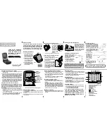
Humminbird 700 series, Operation Manual
The Cisco 700 series offers an extensive range of network switches and routers designed to provide robust connectivity solutions for businesses of all sizes. Enhance your network capabilities with our high-quality devices. Visit manualshive.com to freely download the Quick Start Manual and user manuals for a seamless installation experience.
Share
Download


Reviews:
No comments
Related manuals for 700 series
FF3300P
Brand: Hawkeye Mfg Pages: 2
Elite FS
Brand: Lowrance Pages: 2
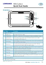
HDS Carbon
Brand: Lowrance Pages: 8
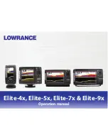
ELITE-4X HDI
Brand: Lowrance Pages: 37

FishHunter 3D/PRO
Brand: Lowrance Pages: 52

Elite-7 Broadband
Brand: Lowrance Pages: 56
Elite-5 DSI
Brand: Lowrance Pages: 64
12 TS
Brand: Lowrance Pages: 92

ELITE TI
Brand: Lowrance Pages: 130


