


5. Oil the shim freely with light engine oil and Install the
bearing and bearing cap to the block with the shim
equally spaced on the bearing. Tighten to 75 foot lbs.
6. Rotate the crankshaft one-half turn by hand; if the
crankshaft drags or if the crankshaft cannot be turned by
hand with a .002" shim in place, but turns freely without
the .002" shim it indicates that the clearance is more than
.0015" and that the standard size bearing can be used. If,
however, the crankshaft turns freely without any drag, it
indicates that the bearing which has the .002" shim stock
is too loose.
7. If bearing is too loose in paragraph 6, remove the .002"
shim and insert a .003" shim as a checking gauge; now if
bearing drags when crankshaft is turned by hand a .001"
undersize bearing can be used.
NOTE: The same procedure can be used for checking .002" ,
.010" or .012" undersize bearings keeping in mind that the
.0005" to .0015" clearance must be maintained.
Main bearings for the 6 cylinder engines are furnished in
standard size and .001", .002", .010" and .012" undersizes.
Bearing upper and lower halves are interchangeable.
However bearing No. 1 is not interchangeable with No. 2, 3
or 4. Bearing shells are stamped with the part number or
size. Bearings should be replaced in pairs; never use a new
bearing half with an old bearing half.
CAUTION: No. 2 and No. 3 bearing caps can be reversed
in error. Always place punch marks on the caps and the
block before removal to insure proper Installation.
1. After the proper bearing sizes have been selected, start the
upper shells in place, and with KMO-734 Bearing Shell
Remover and Replacer Tool entered in oil hole of crank-
shaft and with hinged head of Replacer against bearing
end, rotate crankshaft, pulling the bearing into position,
Figure 14.
NOTE: The bearing shells are held in position by a raised
tongue in the bearing shell which fits into a machined groove
in the bearing cap. When Installing the upper shells, the end
opposite the notched end should be entered first. When
Installing
Installing the bearing cap, the end with the machined
groove should be on the same side and next to the corre-
sponding groove in the cylinder block.
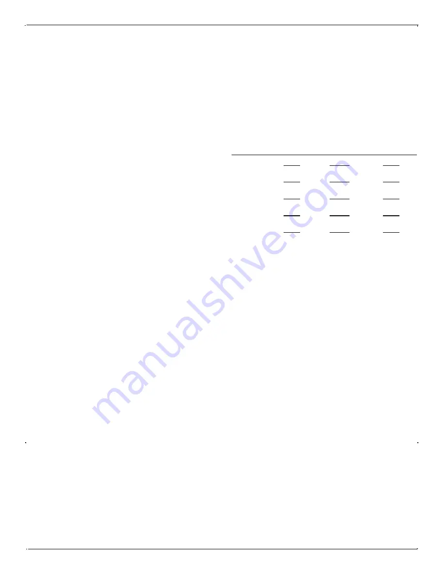
MAIN BEARING, CRANKSHAFT,
AND CAP BORE DIAMETERS
(6 CYLINDER)
REAR MAIN BEARING CAP
Installation:
Check the rear bearing cap oil seal and if replacement of
the seal is necessary, proceed as follows:
1. Crowd the seal material into the outer groove of the bearing cap
by hand and with Main Bearing Oil Seal Installer J-2779, drive
the seal tightly into the groove by tapping handle of tool with a
bronze hammer, Figure 16.
NOTE: Large diameter of the tool cylinder should be to the front of
cap with the lesser dimension compressing the seal at rear of cap.
2. After the seal has been properly seated in the bearing cap and in
the block, and while the tool is still compressing the seal, cut the
seal off flush with the top face of the cap. Make a good clean
straight cut so that no f r ay e d ends will be clamped between
upper and lower caps. DO NOT CUT SEAL TOO SHORT.
The seal must entirely fill the groove; otherwise an oil leak will
occur.
3 - 14 ENGINE
BEAR-
ING
SIZE
SHELL
THICK-
NESS
CRANK-
SHAFT
DIAMETER
CAP
BORE
DIAMETER
Standard
.001 U.S.
.002 U.S.
.010 U.S.
.012 U.S.
.0955
.0952
.0960
.0957
.0965
.0962
.1005
.1002
.1015
.1012
2.4998
2.4988
2.4998
2.4988
2.4978
2.4973
2.4898
2.4893
2.4878
2.4873
2.692
2.691
2.692
2.691
2.692
2.691
2.692
2.691
2.692
2.691
Summary of Contents for 1948 - 1952
Page 1: ...HUDSON SHOP SERVICE MANUAL 1 9 4 8 1 9 5 2...
Page 2: ...This manual courtesy of Hudson Essex Terraplane Club member Drew Meyer...
Page 10: ...VIII...
Page 12: ...1 2 LUBRICATION FIGURE 1...
Page 13: ...LUBRICATION 1 3...
Page 14: ...1 4 LUBRICATION...
Page 46: ...3 4 ENGINE FIGURE 1...
Page 52: ...3 10 ENGINE FIGURE 8...
Page 70: ...3 28 ENGINE FIGURE 32...
Page 71: ...ENGINE 3 29 FIGURE 33...
Page 76: ...3 34 ENGINE FIGURE 40...
Page 78: ...3 36 ENGINE FIGURE 41...
Page 81: ...ENGINE 3 39 FIGURE 44...
Page 119: ...FUEL SYSTEM EXHAUST 4 35 FIGURE 106...
Page 148: ...6 12 ELECTRICAL SYSTEM FIGURE 10...
Page 149: ...ELECTRICAL SYSTEM 6 13...
Page 152: ...6 16 ELECTRICAL SYSTEM FIGURE 12...
Page 180: ...8 2 TRANSMISSION FIGURE 1...
Page 198: ...8 20 TRANSMISSION FIGURE 10...
Page 209: ...OVERDRIVE 9 1...
Page 215: ...OVERDRIVE 9 7 FIGURE 10...
Page 238: ...9 30 OVERDRIVE REFERENCE Source of Information Date Subject...
Page 260: ...11 18 REAR AXLE FIGURE 25...
Page 286: ...12 18 FRONT SUSPENSION REFERENCE Source of Information Date Subject...
Page 306: ...14 8 SPRINGS SHOCK ABSORBERS STABILIZERS REFERENCE Source of Information Date Subject...
Page 322: ...15 16 BRAKES REFERENCE Source of Information Date Subject...
Page 330: ...REFERENCE Source of Information Date Subject...
Page 331: ......
Page 332: ......
Page 333: ......


