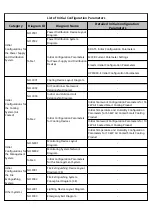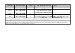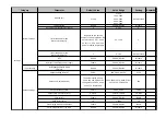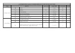
Default Value
Value Range
Setting
Remarks
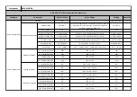
0001
/
Default value
Rated Voltage
400/230 V
100/57 V-115/66 V-120/70 V-208/120 V-220/127 V-230/132
V-240/138 V-277/160 V-347/200 V-380/220 V-400/230 V-
415/240 V-440/254 V-480/277 V
415/240 V
Rated Frequency
50 Hz
50 Hz, 60 Hz
50 Hz
Number of Phases LN1
3 phases with N
3 phases with N/3 phases without N/1 phase
3 phases with N
Number of Phases LN2
3 phases with N
3 phases with N/3 phases without N/1 phase
3 phases with N
Secondary Load
Not Used
Not Used/Opening Only/Opening And Closing
Default Value
Generator Usage
No Generator
No Generator, Generator In Use
Generator In Use
Line priority
Line 1–Switch I
Line 1 – Switch I/Line 2 – Switch II/No Line Priority
Line 1 – Switch
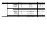
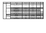
Volt Threshold Min LN1
-20%
-30% to -5%
-10%
Volt Threshold Min LN2
-20%
-30% to -5%
-10%
Volt Threshold Max LN1
+20%
+5% to +30%
+10%
Volt Threshold Max LN2
+20%
+5% to +30%
+10%
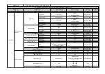
Volt Hysteresis Min LN1
-8%
-29% to -4%, step 1%
-8%
Volt Hysteresis Min LN2
-8%
-29% to -4%, step 1%
-8%
Volt Hysteresis Max LN1
+8%
+4% to +29%, step 1%
+8%
Volt Hysteresis Max LN2
+8%
+4% to +29%, step 1%
+8%
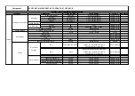
Freq Threshold Min LN1
-5%
-10% to -1%
-5%
Freq Threshold Min LN2
-5%
-10% to -1%
-5%
Freq Threshold Max LN1
+5%
+1% to +10%
+5%
Freq Threshold Max LN2
+5%
+1% to +10%
+5%
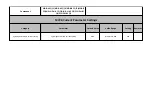
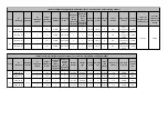
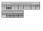
Parameter
Component
MDB-A/MDB-B
Category
Configuration attributes
Voltage Thresholds
System Configuration
ABB 8D ATS Initial Configuration Parameters
Device Configuration
Voltage Hysteresis
Frequency Thresholds
Password
Summary of Contents for FusionDC1000B
Page 45: ......
Page 46: ......
Page 51: ......
Page 52: ......
Page 53: ......
Page 54: ......
Page 55: ......
Page 56: ......
Page 59: ......
Page 60: ......
Page 61: ......
Page 68: ......
Page 69: ......
Page 70: ......
Page 71: ......
Page 72: ......
Page 73: ......
Page 77: ......
Page 82: ......
Page 83: ......
Page 92: ......
Page 93: ......
Page 94: ......
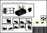
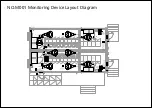
Page 98: ...Window CB DH 1 Window CB PR B1 ECC NO M001 Monitoring Device Layout Diagram ...
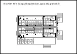
Page 110: ...NO F002 Fire Extinguishing System Conceptual Diagram CE ...
Page 111: ...NO F002 Fire Extinguishing System Conceptual Diagram CE ...
Page 112: ...NO F002 Fire Extinguishing System Conceptual Diagram CE ...
Page 113: ...NO F002 Fire Extinguishing System Conceptual Diagram CE ...
Page 114: ...NO F002 Fire Extinguishing System Conceptual Diagram CE ...
Page 115: ...NO F002 Fire Extinguishing System Conceptual Diagram CE ...
Page 116: ...NO F002 Fire Extinguishing System Conceptual Diagram CE ...
Page 117: ...NO F002 Fire Extinguishing System Conceptual Diagram CE ...
Page 118: ...NO F002 Fire Extinguishing System Conceptual Diagram CE ...
Page 119: ......
Page 120: ...Window CB DH 1 Window CB PR B1 EXIT Exit DH 3 NO F003 Emergency Exit Diagram ...

