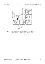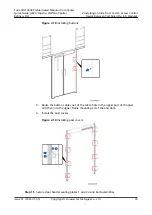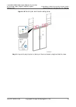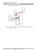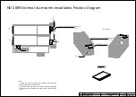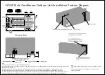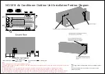
Note:
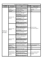
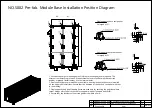
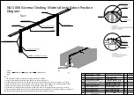
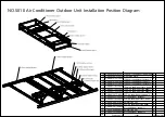
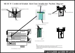
1. The installation sequence of external sealing materials is as follows:
1) Install T-shaped rubber strips at the top and end, as shown in the figure.
2) Attach waterproof rolls to the top and end and apply sealant to the gap of the rolls, as shown in the figure.
3) Install the top cover, front cover, and rear cover, and secure them using GB9074_17-8_M10X40_S_ZNAL screws.
4) Install the corner fitting cover and secure it using GB9074_4-88_M4X12_S screws.
5) Attach the top clamping plate gap sealing roll and screw hole roll, and apply sealant to the gap of the rolls.
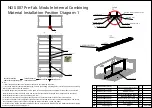
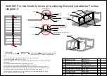
6) After all external sealing kits are installed, install internal bottom sealing kits for combined modules by referring to
NO.S007Pre-fab. Module Internal Combining Material Installation Position Diagram-1.
Install
rubber
strip
Apply sealant
Attach roll
Install cover
t=2mm
DKBA82990596.ASM
6
End clamping plate
DKBA82990592.ASM
6
Top clamping plate
No.
Drawing No.
Item
Qty
Remarks
1
2
GB9074_4-88_M4X12_S
8
Stainless steel screw
3
4
DKBA04853056_20000
1
GB9074_17-88_M10X40_S_ZNAL
48
T-shaped rubber strip
5
6
DKBA04853091_20000X500
1
Waterproof roll
7
Stainless steel screw
NO.S006 External Sealing Material Installation Position
Diagram
5.GB9074_17-88_M10X40_S_ZNAL
(48 PCS)
4.GB9074_4-88_M4X12_S(8 PCS)
A2
A1
DKBA82990593.ASM
Corner fitting cover
4
8
9
DKBA04853091_100X800
DKBA04853091_100X800
Screw hole roll
Clamping plate gap sealing roll
12
5
t=2mm
t=2mm
Summary of Contents for FusionDC1000B
Page 45: ......
Page 46: ......
Page 51: ......
Page 52: ......
Page 53: ......
Page 54: ......
Page 55: ......
Page 56: ......
Page 59: ......
Page 60: ......
Page 61: ......
Page 68: ......
Page 69: ......
Page 70: ......
Page 71: ......
Page 72: ......
Page 73: ......
Page 77: ......
Page 82: ......
Page 83: ......
Page 92: ......
Page 93: ......
Page 94: ......
Page 98: ...Window CB DH 1 Window CB PR B1 ECC NO M001 Monitoring Device Layout Diagram ...
Page 110: ...NO F002 Fire Extinguishing System Conceptual Diagram CE ...
Page 111: ...NO F002 Fire Extinguishing System Conceptual Diagram CE ...
Page 112: ...NO F002 Fire Extinguishing System Conceptual Diagram CE ...
Page 113: ...NO F002 Fire Extinguishing System Conceptual Diagram CE ...
Page 114: ...NO F002 Fire Extinguishing System Conceptual Diagram CE ...
Page 115: ...NO F002 Fire Extinguishing System Conceptual Diagram CE ...
Page 116: ...NO F002 Fire Extinguishing System Conceptual Diagram CE ...
Page 117: ...NO F002 Fire Extinguishing System Conceptual Diagram CE ...
Page 118: ...NO F002 Fire Extinguishing System Conceptual Diagram CE ...
Page 119: ......
Page 120: ...Window CB DH 1 Window CB PR B1 EXIT Exit DH 3 NO F003 Emergency Exit Diagram ...

