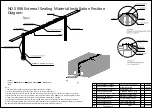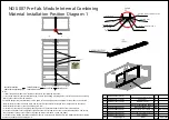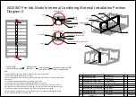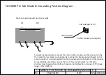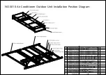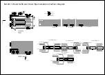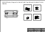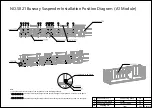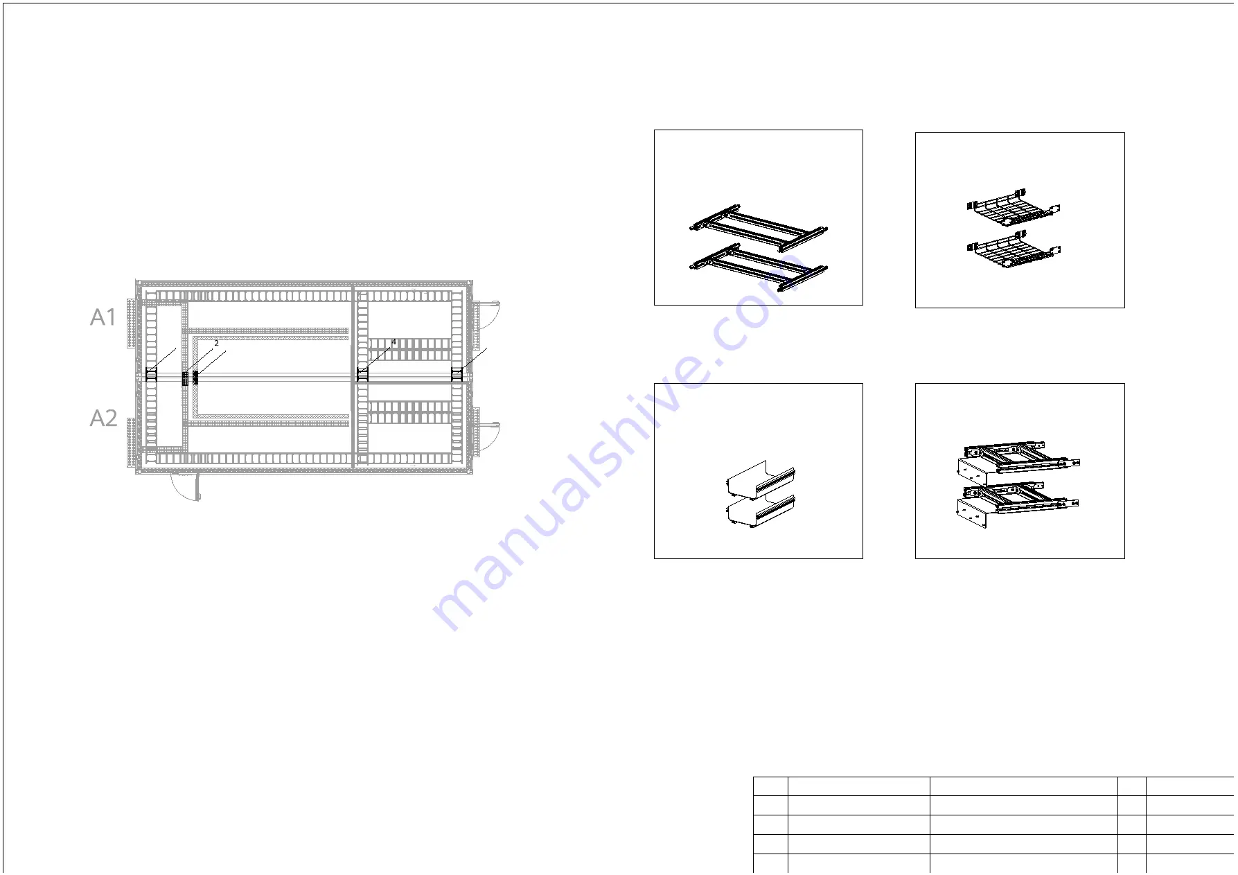
NO.S020 Position Diagram for Internal Cable Trays Between Combined Pre-fab.
Modules
1. Aluminum profile cable tray
DKBA61595925.ASM
1
Aluminum profile cable tray
DKBA61585783.ASM
2
Mesh cable tray
No.
Drawing No.
Item
Qty
Remarks
1
2
DKBA61595926.ASM
1
Optical fiber cable trough
DKBA83117985.ASM
1
Front aluminum profile cable tray
3
4
With connector
With connector
With connector
With connector
34
33
32
31
30
29
28
27
26
25
34
33
32
31
30
29
28
27
26
25
34
33
32
31
30
29
28
27
26
25
34
33
32
31
30
29
28
27
26
25
3. Optical fiber cable trough
2. Mesh cable tray
4. Front aluminum profile cable tray
1
3
4
Summary of Contents for FusionDC1000B
Page 45: ......
Page 46: ......
Page 51: ......
Page 52: ......
Page 53: ......
Page 54: ......
Page 55: ......
Page 56: ......
Page 59: ......
Page 60: ......
Page 61: ......
Page 68: ......
Page 69: ......
Page 70: ......
Page 71: ......
Page 72: ......
Page 73: ......
Page 77: ......
Page 82: ......
Page 83: ......
Page 92: ......
Page 93: ......
Page 94: ......
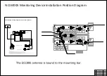
Page 98: ...Window CB DH 1 Window CB PR B1 ECC NO M001 Monitoring Device Layout Diagram ...
Page 110: ...NO F002 Fire Extinguishing System Conceptual Diagram CE ...
Page 111: ...NO F002 Fire Extinguishing System Conceptual Diagram CE ...
Page 112: ...NO F002 Fire Extinguishing System Conceptual Diagram CE ...
Page 113: ...NO F002 Fire Extinguishing System Conceptual Diagram CE ...
Page 114: ...NO F002 Fire Extinguishing System Conceptual Diagram CE ...
Page 115: ...NO F002 Fire Extinguishing System Conceptual Diagram CE ...
Page 116: ...NO F002 Fire Extinguishing System Conceptual Diagram CE ...
Page 117: ...NO F002 Fire Extinguishing System Conceptual Diagram CE ...
Page 118: ...NO F002 Fire Extinguishing System Conceptual Diagram CE ...
Page 119: ......
Page 120: ...Window CB DH 1 Window CB PR B1 EXIT Exit DH 3 NO F003 Emergency Exit Diagram ...

