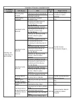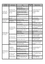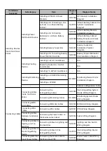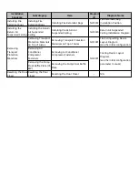
Installation
Sequence
Subcategory
Item
Diagram
ID
Diagram Name
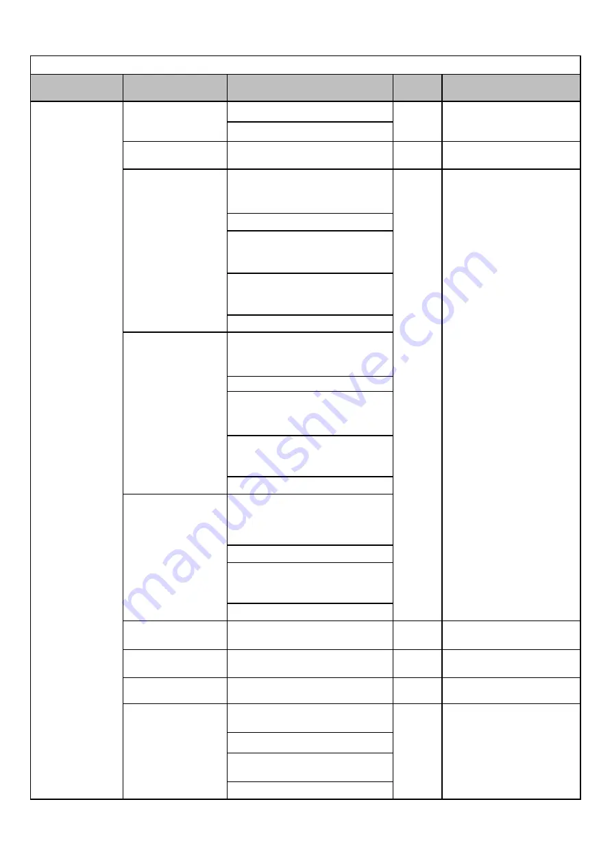
Installing Pre-fab. Module Bases
Installing Twistlocks
Removing the
Transport
Removing the Transport
Protection Cover
-
N/A
Removing the Side Panels for
Combining with the Next
Pre-fab. Module
Installing Supportive Columns
Installing Distance Blocks for
Combining with the Next
Pre-fab. Module
Hoisting and Securing Pre-fab.
Modules (Mounting Base
Solution)
Removing Supportive Columns
Removing Side Panels for
Combining Pre-fab. Modules at
Both
Installing Supportive Columns
Installing Distance Blocks for
Combining with the Next
Pre-fab. Module
Hoisting and Securing Pre-fab.
Modules (Mounting Base
Solution)
Removing Supportive Columns
Removing the Side Panels for
Combining with the Previous
Pre-fab. Module
Installing Supportive Columns
Hoisting and Securing Pre-fab.
Modules (Mounting Base
Solution)
Removing Supportive Columns
Securing Pre-fab.
Modules
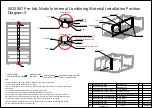
Securing Pre-fab. Modules
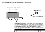
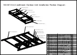
NO.S005
Pre-fab. Module Securing
Position Diagram
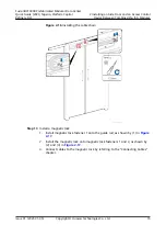
Obtaining the
Emergent Backup
Obtaining the Emergent Backup
Key
-
N/A
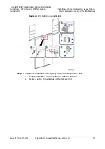
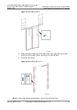
Disabling the Door
Closer
Disabling the Door Closer
-
N/A
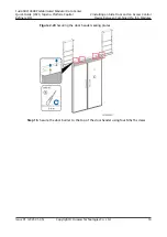
Installing External Sealing Rubber
Strips
Installing Waterproof Rolls
Installing Rubber Strip Clamping
Plates
Installing Corner Fitting Covers
Checklist of Devices Installed Onsite
Installing and
Combining Pre-
fab. Modules
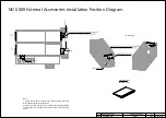
NO.S002
Mounting Base
Solution
Installing Pre-fab.
Modules
Installing Pre-fab.
Modules
Installing Pre-fab.
Modules
Installing External
Sealing Materials for
Combined Pre-fab.
Modules
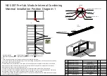
Pre-fab. Module
Combination Diagram
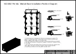
NO.S004
Pre-fab. Module Base
Installation Position
Diagram
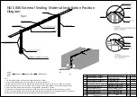
External Sealing Material
Installation Position
Diagram
NO.S006
Summary of Contents for FusionDC1000B
Page 45: ......
Page 46: ......
Page 51: ......
Page 52: ......
Page 53: ......
Page 54: ......
Page 55: ......
Page 56: ......
Page 59: ......
Page 60: ......
Page 61: ......
Page 68: ......
Page 69: ......
Page 70: ......
Page 71: ......
Page 72: ......
Page 73: ......
Page 77: ......
Page 82: ......
Page 83: ......
Page 92: ......
Page 93: ......
Page 94: ......
Page 98: ...Window CB DH 1 Window CB PR B1 ECC NO M001 Monitoring Device Layout Diagram ...
Page 110: ...NO F002 Fire Extinguishing System Conceptual Diagram CE ...
Page 111: ...NO F002 Fire Extinguishing System Conceptual Diagram CE ...
Page 112: ...NO F002 Fire Extinguishing System Conceptual Diagram CE ...
Page 113: ...NO F002 Fire Extinguishing System Conceptual Diagram CE ...
Page 114: ...NO F002 Fire Extinguishing System Conceptual Diagram CE ...
Page 115: ...NO F002 Fire Extinguishing System Conceptual Diagram CE ...
Page 116: ...NO F002 Fire Extinguishing System Conceptual Diagram CE ...
Page 117: ...NO F002 Fire Extinguishing System Conceptual Diagram CE ...
Page 118: ...NO F002 Fire Extinguishing System Conceptual Diagram CE ...
Page 119: ......
Page 120: ...Window CB DH 1 Window CB PR B1 EXIT Exit DH 3 NO F003 Emergency Exit Diagram ...

