Module Exit Button
Module Emergency Button
Monitoring Wiring diagram of Access Actuator
LOCK
GND
GATE
GND
AI/DI_2
WG_1
WG_2
AI/DI_1
COM1
COM2
POE
1 2 3 4
ADDRESS
PGND -48V RTN
Access Actuator
NC
C
+
-
Magnetic Lock
Magnetic Lock
GND
+
GND
+
RED
BLACK
BLUE
WHITE
RED
BLACK
YELLOW
YELLOW
RED
BLACK
RED
BLACK
POE_
PDU
Technical Requirements Notes:
1. The magnetic lock is connected to the emergency button using an electronic and electrical cable.
2. Crimp cord end terminals at both ends of the cable and connect them using interconnection terminals.
3. The door open button is connected to the access control actuator using a network cable.
4. Crimp RJ45 connectors at both ends of the network cable using the T568B connection method. Connect the network port connector to the door button.
5. Connect the card reader to the access actuator using a network cable.
6. Crimp RJ45 connectors at both ends of the network cable using the T568B connection method.
1
2
3
4
RED
male
female
YELLOW
YELLOW
BLACK
RED
RED
BLACK
RED
RED
BLACK
BLACK
1
2
3
4
RED
BLACK
RED BLACK
Yellow
Red
Green
White
Brown
Black
Orange
Green-white
Blue
Blue-white
Green
Brown
Reader(IC card)
male
female
male
female
male
female
No.
Name
Quantity
1
SERVER
1pcs
2
Hard Disk
1pcs
3
Directional Antenna,RP-SMA-J
3pcs
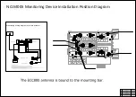
NO.M005 Monitoring Device Installation Position Diagram
Summary of Contents for FusionDC1000B
Page 45: ......
Page 46: ......
Page 51: ......
Page 52: ......
Page 53: ......
Page 54: ......
Page 55: ......
Page 56: ......
Page 59: ......
Page 60: ......
Page 61: ......
Page 68: ......
Page 69: ......
Page 70: ......
Page 71: ......
Page 72: ......
Page 73: ......
Page 77: ......
Page 82: ......
Page 83: ......
Page 92: ......
Page 93: ......
Page 94: ......
Page 98: ...Window CB DH 1 Window CB PR B1 ECC NO M001 Monitoring Device Layout Diagram ...
Page 110: ...NO F002 Fire Extinguishing System Conceptual Diagram CE ...
Page 111: ...NO F002 Fire Extinguishing System Conceptual Diagram CE ...
Page 112: ...NO F002 Fire Extinguishing System Conceptual Diagram CE ...
Page 113: ...NO F002 Fire Extinguishing System Conceptual Diagram CE ...
Page 114: ...NO F002 Fire Extinguishing System Conceptual Diagram CE ...
Page 115: ...NO F002 Fire Extinguishing System Conceptual Diagram CE ...
Page 116: ...NO F002 Fire Extinguishing System Conceptual Diagram CE ...
Page 117: ...NO F002 Fire Extinguishing System Conceptual Diagram CE ...
Page 118: ...NO F002 Fire Extinguishing System Conceptual Diagram CE ...
Page 119: ......
Page 120: ...Window CB DH 1 Window CB PR B1 EXIT Exit DH 3 NO F003 Emergency Exit Diagram ...

