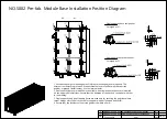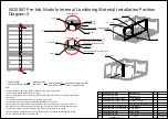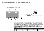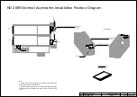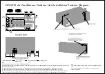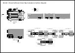
NO.S002 Pre-fab. Module Base Installation Position Diagram
Enlarged at 5:1
Single-capacity base component
Enlarged at 5:1
Dual-capacity base component
260
340
300
480
560
620
400
440
200
260 340
290
370
250
430
200
400
300
Single-capacity
base
A1
A2
Single-capacity
base
Single-capacity
base
Single-capacity
base
Single-capacity
base
Single-capacity
base
Single-capacity
base
Single-capacity
base
Single-capacity
base
Single-capacity
base
1. Each base has eight mounting holes. Only four mounting holes are required. The
external four holes are preferred. If the external holes are conflict with the concrete
podium or ground reinforcement, use the internal holes.
2. Dual-capacity bases are installed in the middle, and single-capacity bases are installed
on the upper and lower sides. Ensure that the direction of the bases is consistent with that
in the drawing.
3. Single-capacity and dual-capacity bases are used only for securing the positions where
corner fittings exist. Others are used for support (without T-shaped bolts M20).
DKBA40703509.ASM
5
Single-capacity base component
DKBA40703508.ASM
10
Dual-capacity base component
No.
Drawing No.
Item
Qty
Remarks
1
2
Summary of Contents for FusionDC1000B
Page 45: ......
Page 46: ......
Page 51: ......
Page 52: ......
Page 53: ......
Page 54: ......
Page 55: ......
Page 56: ......
Page 59: ......
Page 60: ......
Page 61: ......
Page 68: ......
Page 69: ......
Page 70: ......
Page 71: ......
Page 72: ......
Page 73: ......
Page 77: ......
Page 82: ......
Page 83: ......
Page 92: ......
Page 93: ......
Page 94: ......
Page 98: ...Window CB DH 1 Window CB PR B1 ECC NO M001 Monitoring Device Layout Diagram ...
Page 110: ...NO F002 Fire Extinguishing System Conceptual Diagram CE ...
Page 111: ...NO F002 Fire Extinguishing System Conceptual Diagram CE ...
Page 112: ...NO F002 Fire Extinguishing System Conceptual Diagram CE ...
Page 113: ...NO F002 Fire Extinguishing System Conceptual Diagram CE ...
Page 114: ...NO F002 Fire Extinguishing System Conceptual Diagram CE ...
Page 115: ...NO F002 Fire Extinguishing System Conceptual Diagram CE ...
Page 116: ...NO F002 Fire Extinguishing System Conceptual Diagram CE ...
Page 117: ...NO F002 Fire Extinguishing System Conceptual Diagram CE ...
Page 118: ...NO F002 Fire Extinguishing System Conceptual Diagram CE ...
Page 119: ......
Page 120: ...Window CB DH 1 Window CB PR B1 EXIT Exit DH 3 NO F003 Emergency Exit Diagram ...

