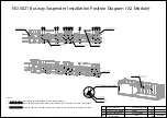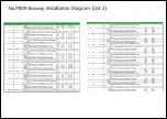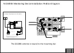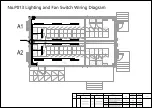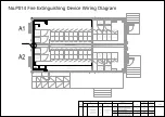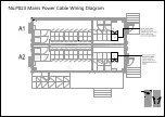
Air outlet window
Air outlet window
Fan-DH-3
Fan-DH-2
Fan-DH-1
Window CB-PR-A1
Air outlet window
LANSWITCH
ECC
SEVER
DDC
VCN
LANSWITCH
Monitoring Wiring diagram of NMW
Technical Requirements Notes:
1. Network ports are connected using network cables.
2. Both ends of the network cable are RJ45 connectors.
3. Direct cable connection using T568B;
4. The power cable is an electronic and electrical cable. The two ends of the cable are crimped and connected using a power connector.
Collector_ECC800P
ECC800 BACK
Monitoring Wiring diagram of LAN Swtich
Technical Requirements Notes:
1. Use network cables.
2. Both ends of the network cable are RJ45 connectors.
3. Direct cable connection using T568B;
LAN Switch
LAN Switch
1
A101
LanS-PR-A1
A102
LAN Switch-DH-1
25050057
Twisted-Pair Cable,100ohm,Category 5e,FTP,0.52mm,24AWG,8Cores,4Pairs,PANTONE 430U,Use with Plug:14080097
1
PCS
Install VCN onsite.
2
A101
GIU-DH-A2
A102
GIU-DH-B1
25050057
Twisted-Pair Cable,100ohm,Category 5e,FTP,0.52mm,24AWG,8Cores,4Pairs,PANTONE 430U,Use with Plug:14080097
1
PCS
3
A101
A102
25033402
Electronic|Electric Cable,300V,UL3385,16AWG,Tin Plating,Black,LSZH,UL
1
PCS
5
A102
A101
25050057
Twisted-Pair Cable,100ohm,Category 5e,FTP,0.52mm,24AWG,8Cores,4Pairs,PANTONE 430U,Use with Plug:14080097
1
PCS
A102
A101
1
PCS
Collector_ECC800-DH-1
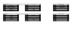
No.
Module
Input device
Module
Output device
Code No.
Description
QTY
Unit
Input
Output
6
GIU-DH-A2
GIU-DH-B1
GIU-DH-A1
GIU-DH-A1
Collector_ECC800-DH-1
4
A101
A102
25033402-005 Electronic|Electric Cable,300V,UL3385,16AWG,Tin Plating,Red,LSZH,UL
1
PCS
GIU-DH-A2
GIU-DH-B1
25033402
Electronic|Electric Cable,300V,UL3385,16AWG,Tin Plating,Black,LSZH,UL
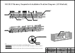
NO.M006 Monitoring Onsite Wiring Diagram
Summary of Contents for FusionDC1000B
Page 45: ......
Page 46: ......
Page 51: ......
Page 52: ......
Page 53: ......
Page 54: ......
Page 55: ......
Page 56: ......
Page 59: ......
Page 60: ......
Page 61: ......
Page 68: ......
Page 69: ......
Page 70: ......
Page 71: ......
Page 72: ......
Page 73: ......
Page 77: ......
Page 82: ......
Page 83: ......
Page 92: ......
Page 93: ......
Page 94: ......
Page 98: ...Window CB DH 1 Window CB PR B1 ECC NO M001 Monitoring Device Layout Diagram ...
Page 110: ...NO F002 Fire Extinguishing System Conceptual Diagram CE ...
Page 111: ...NO F002 Fire Extinguishing System Conceptual Diagram CE ...
Page 112: ...NO F002 Fire Extinguishing System Conceptual Diagram CE ...
Page 113: ...NO F002 Fire Extinguishing System Conceptual Diagram CE ...
Page 114: ...NO F002 Fire Extinguishing System Conceptual Diagram CE ...
Page 115: ...NO F002 Fire Extinguishing System Conceptual Diagram CE ...
Page 116: ...NO F002 Fire Extinguishing System Conceptual Diagram CE ...
Page 117: ...NO F002 Fire Extinguishing System Conceptual Diagram CE ...
Page 118: ...NO F002 Fire Extinguishing System Conceptual Diagram CE ...
Page 119: ......
Page 120: ...Window CB DH 1 Window CB PR B1 EXIT Exit DH 3 NO F003 Emergency Exit Diagram ...

