DKBA81865798.ASM
42
Corner fitting
GB9074_13-88_M6X16
28
Screw
No.
Drawing No.
Item
Qty
Remarks
1
2
3
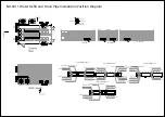
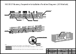
NO.S021 Busway Suspender Installation Position Diagram (A1 Module)
DKBA04853262_E-1
Connecting plate
28
Note:
1. Install the upper corner fittings of the suspenders in the following sequence:
1) Install the lower-layer straight section corner fittings of the suspenders, as shown in the figure.
2) Install the upper-layer straight section corner fittings of the suspendiers, as shown in the figure.
GB9074_13-88_M6X16
Summary of Contents for FusionDC1000B
Page 45: ......
Page 46: ......
Page 51: ......
Page 52: ......
Page 53: ......
Page 54: ......
Page 55: ......
Page 56: ......
Page 59: ......
Page 60: ......
Page 61: ......
Page 68: ......
Page 69: ......
Page 70: ......
Page 71: ......
Page 72: ......
Page 73: ......
Page 77: ......
Page 82: ......
Page 83: ......
Page 92: ......
Page 93: ......
Page 94: ......
Page 98: ...Window CB DH 1 Window CB PR B1 ECC NO M001 Monitoring Device Layout Diagram ...
Page 110: ...NO F002 Fire Extinguishing System Conceptual Diagram CE ...
Page 111: ...NO F002 Fire Extinguishing System Conceptual Diagram CE ...
Page 112: ...NO F002 Fire Extinguishing System Conceptual Diagram CE ...
Page 113: ...NO F002 Fire Extinguishing System Conceptual Diagram CE ...
Page 114: ...NO F002 Fire Extinguishing System Conceptual Diagram CE ...
Page 115: ...NO F002 Fire Extinguishing System Conceptual Diagram CE ...
Page 116: ...NO F002 Fire Extinguishing System Conceptual Diagram CE ...
Page 117: ...NO F002 Fire Extinguishing System Conceptual Diagram CE ...
Page 118: ...NO F002 Fire Extinguishing System Conceptual Diagram CE ...
Page 119: ......
Page 120: ...Window CB DH 1 Window CB PR B1 EXIT Exit DH 3 NO F003 Emergency Exit Diagram ...

