background image

 HP Vectra PC User's Guide

3   Installing Accessories In Your PC  

••

  42

Installing Memory

Main Memory

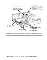
Your PC is supplied with 4 MB or 8 MB of main memory, depending on the model. If you
need more main memory to run your application software, you can install up to a total of 64
MB.

Main memory is available in modules of 4 MB, 8 MB, 16 MB, or 32 MB. For a list of available
modules, refer to “Supported HP Accessories.” The modules can be installed in any
combination, and any order.

WARNING

Static electricity can damage electronic components. Turn all equipment off.
Don’t let your clothes touch the accessory.

To equalize the static electricity, rest the accessory bag on top of the power
supply unit while you are removing the accessory from the bag. Handle the
accessory as little as possible and with care.

Summary of Contents for Vectra VE4

Page 1: ...exible Disks Using the HP User Tools What s Behind the Icons Finding More Information About Your PC Using Power Management Configuring Power Management in Windows Activating Sleep Mode in Windows Understanding the Desktop Management Interface Personalizing Your Mouse Tips for Using Your PC 3 Installing Accessories In Your PC Supported HP Accessories Removing and Replacing the Cover Removing the Co...

Page 2: ...ssage Appears Power On Errors That May Prevent the PC from Starting BIOS and Operating System Messages Hardware Problems The Display Does Not Work If Your Display is Blurred or Unreadable If You Cannot Activate any Video Resolution Higher than 640 x 480 The Keyboard or Mouse Does Not Work The Printer Does Not Work The Flexible Disk Drive Does Not Work The Hard Disk Does Not Work The Hard Disk Acti...

Page 3: ...t Getting Support from your HP Reseller HP Support Pack Hewlett Packard Information Services HP Internet FTP Library Service World Wide Web HP Forum on CompuServe Hewlett Packard Telephone Support If You Need to Contact Hewlett Packard Glossary Definitions 7 Regulatory Information and Warranty Regulatory Information FCC for USA only Notice for Canada Safety Warning for the USA and Canada Notice fo...

Page 4: ...HP Vectra PC User s Guide 1 Setting Up Your PC 4 Printed Manual Information 1995 Hewlett Packard Company ...

Page 5: ...er Corporation CompuServe is a registered trademark of CompuServe Incorporated Logitech is a trademark of Logitech Inc Microsoft and MS DOS are U S registered trademarks of Microsoft Corporation OS 2 is a trademark of International Business Machines Corporation Windows and Windows NT are trademarks of Microsoft Corporation ...

Page 6: ...HP Vectra PC User s Guide 1 Setting Up Your PC 6 1 Setting Up Your PC ...

Page 7: ...e the computer on a sturdy desk close to easily accessible power outlets and with enough space for the keyboard mouse and any other accessories 3 Position the computer so that its rear connectors are easily accessible 4 Place the display on top of the computer If you have a large display place it next to the computer WARNING If you are in any doubt that you cannot lift the display safely do not at...

Page 8: ...onnecting the Mouse Display and Keyboard 1 Connect the mouse keyboard and display cables to the back of the computer The connectors are shaped to go in one way only 2 Tighten the display cable attachment screws Mouse Cable Keyboard Cable Display Cable ...

Page 9: ... Setting Up Your PC 9 Connecting a Printer or Plotter If you have a printer or plotter connect its cable to the back of the computer and tighten the attachment screws Connector for Parallel Printer Connectors for Serial Printers ...

Page 10: ...power cable to a grounded outlet WARNING For your safety always connect the equipment to a grounded wall outlet Always use a power cable with properly grounded plugs such as the one provided with this equipment or one in compliance with your national regulation This PC has been designed to operate on all power systems including IT power systems It is disconnected from the power by removing the pow...

Page 11: ...s any errors found If an error is detected see If a Power On Error Message Appears 3 The software initialization routine starts It displays the software license agreement and gives you an opportunity to read Working in Comfort ergonomic advice for computer users You may be asked to enter information during the intiialization routine for example The name of the person who will use the computer and ...

Page 12: ...e picture does not fill the screen or is not centered adjust it using the controls on the display Refer to the display s manual for details Adjust the display s brightness to your needs 6 Set the keyboard angle and mouse to comfortable positions 7 After the initialization has finished fill in your Warranty Registration card ...

Page 13: ...s of receiving your PC using new diskettes These diskettes can then be used to restore the preloaded software to your PC in case of corrupted files 1 Double click the mouse on the Master Diskette Creation Utility icon in the HPutils group in the Windows Program Manager 2 Follow the screen messages to create master diskettes of your preloaded software The messages will tell you how many diskettes a...

Page 14: ...HP Vectra PC User s Guide 2 Using Your PC 14 2 Using Your PC ...

Page 15: ...ctra PC User s Guide 2 Using Your PC 15 Error Bookmark not defined Using the HP Setup Program The integrated ROM based Setup program displays your PC s configuration and allows you to set certain parameters ...

Page 16: ...on as the power on system hardware test has passed the Flexible Disk Drives test 3 The Setup program will appear Setup Version xx Administrator Password Not Set User Password Not Set Date YYYY mm dd 1995 01 07 Flexible Drive 1 1 44 MB Time hh mm ss 12 04 30 Flexible Drive 2 none Power on Numlock State On Start from FDD Enabled Key Autorepeat Medium If a password has been set you will be prompted t...

Page 17: ...ld determines if the numeric keys on the right of the keyboard are set to numeric values On or cursor control Off when the PC is started Key Autorepeat This field determines the speed that a key repeats itself when the key is held down Options available are Slow Medium and Fast The other fields are explained later in the manual at the place where you may need to modify the settings For easy refere...

Page 18: ...prevent the PC being started in your absence and prevent modifications being made to your system configuration Disabling startup from the flexible disk drive hard disk drives or both Disabling the flexible disk drive or drives so that data cannot be copied in your absence Locking the computer s cover to prevent unauthorized access to the internal components The following sections describe how to p...

Page 19: ...o the configuration settings in the Setup program even if the User password is known If this password is set a forgotten User password can be reset from the Setup program When either or both passwords are set the Setup program can be started and the settings displayed but no changes are allowed unless the correct password is entered CAUTION A jumper is provided on the system board that allows forg...

Page 20: ...our password press ENTER twice NOTE It is recommended that you set a password that you can easily remember If you forget a password see Software Problems 4 Press F3 to save your password and exit the Setup program 5 When you have set a User password the next time the PC is started the power on prompt is displayed Type your User password and press ENTER to use the PC You have three chances to enter...

Page 21: ...HP Vectra PC User s Guide 2 Using Your PC 21 Error Bookmark not defined Setting Other Security Features ...

Page 22: ...are set the Administrator password must be entered to change the setting 1 Start the Setup program see Using the HP Setup Program 2 If a password has not been set set one now see How to Set a Password 3 Use the arrow keys to move the highlight to the Start from FDD field if you wish to disable starting from the flexible disk drive 4 Use the F8 key to disable the function 5 Repeat steps 2 and 3 usi...

Page 23: ...passwords are set the Administrator password must be entered to change the setting The following sections describe how to perform these actions 1 Start the Setup program see Using the HP Setup Program 2 If a password has not been set set one now see How to Set a Password 3 Use the arrow keys to move the highlight to the Flexible Disk Drivesfield 4 Use the F8 key to disable the drive s 5 If you do ...

Page 24: ...about your PC and allow you to configure your printer and display settings To access the HP User Tools 1 Double click on the HPutils group icon in Windows Program Manager to display the Hewlett Packard utilities 2 Double click on the HP User Tools icon to display the HP User Tools utility 3 Click on the icon of the tool that you wish to use ...

Page 25: ...efresh rate Click on this icon if you change your display Disable the Plug and Play field in the Setup program to retain your settings next time you start the PC Click on this icon if you want to change the name of the user of your PC If a user name has already been entered during the software initialization routine you can change it Click on this icon to set up and configure your printer Use this...

Page 26: ... that explains the key features of your PC provides information about supplied software and describes the procedures for installing accessories To view the document 1 Double click on the HPutils group icon in Windows Program Manager to display the Hewlett Packard utilities 2 Double click on the Discover Your HP Vectra VE 4 xx PC icon to display the document ...

Page 27: ...e of inactivity reduces power consumption to 27 Watts by blanking the display The PC returns to normal operation as soon as any key on the keyboard is pressed Sleep mode which can be set to occur at a specific time reduces power consumption to 22 Watts by blanking the display and switching off the hard disk drive and processor The PC returns to normal operation up to 15 seconds after any key on th...

Page 28: ...ialog box 4 Select the Advanced mode 5 Click on Options and the Setup Power Management dialog box appears 6 Set the Standby timeout 30 minutes by default the Sleep At time set to Off by default or both NOTE For more information about the Windows Power Management utility click on the Help button in the Setup Power Management dialog box 7 Click on OK to close the Setup Power Management dialog box 8 ...

Page 29: ... the time specified has elapsed To return to full power press any key Power Management in DOS 1 Start the Setup program see Using the HP Setup Program 2 Use the arrow keys to move the highlight to the DOS APM Standbyitem 3 Set the Standby timeout required 4 Use the F3 key to save your settings and exit the Setup program For more information about the DOS power management utility at the DOS prompt ...

Page 30: ...stem used by your PC the number of available accessory board slots All of this information is stored in a Management Information Format MIF file installed on your PC as part of the DMI package To install the DMI demonstration program and learn more about the Desktop Management Interface 1 Double click on the HP DMI group icon in the Windows Program Manager 2 Double click on the DMI Readme icon for...

Page 31: ...led Windows software which lets you personalize the functionality of your mouse 1 Double click on the Mouse Software group icon to display the Mouse Software 2 Double click on the Mouse Control Center icon to display the Mouse Control Center 3 Click on the Help button for more information about the Mouse Control Center ...

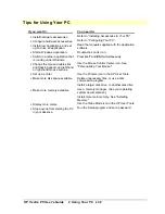
Page 32: ...and ESC simultaneously Change the mouse double click and tracking speed and left hand or right hand mouse buttons Use the Mouse Control Center icon See Personalizing Your Mouse Set up a printer Use the Printers icon in the HP User Tools Make more disk space available Delete unnecessary files or use a disk compression program Install a larger disk drive or another disk drive Make more memory availa...

Page 33: ...HP Vectra PC User s Guide 3 Installing Accessories In Your PC 33 3 Installing Accessories In Your PC ...

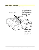
Page 34: ...rd Disk Drives 270 MB IDE order D2388A 540 MB IDE order D2389A Front Access Devices 5 25 inch 1 2 MB flexible disk drive half height order D2881B 3 5 inch 1 44 MB flexible disk drive one third height order D2035B IDE CD ROM order D2889A B Mounting Trays and Rails for Front Access Devices 3 5 inch disk drive trays order D3566A 5 25 inch disk drive rails order D2880A ...

Page 35: ...us single order 27247B 16TL Plus order 27252A 10 100VG Selectable ISA Adapter order J2573A Main Memory Modules 70 ns 4 MB order D2690A 8 MB order D2691A 16 MB order D2297A 32 MB order D2298A Second Level Cache Memory Module 256 KB order D2465A Video Memory Upgrade 1 MB order D3500A WARNING For your safety never remove the computer s cover without first removing the power cable and any connection t...

Page 36: ...E If you are replacing the supplied hard disk drive or installing a non plug and play accessory board ensure that you have carried out the prerequisite activities before removing the cover see Installing or Replacing an IDE Hard Disk Drive in the Rear Shelf and Installing Accessory Boards respectively ...

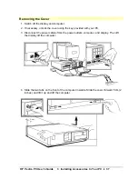
Page 37: ...puter 2 If necessary unlock the cover using the key provided with your PC 3 Disconnect the power cables from the power outlets computer and display Then lift the display off the computer 4 Slide the two tabs on the front of the computer inwards Slide the cover forward 5 cm 2 inches and lift it up and off the computer ...

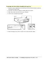
Page 38: ...talled all your accessories and that all internal cables are properly connected and safely routed 2 Lower the cover onto the computer and firmly slide it into position 3 Slide the two tabs on the front of the cover outwards 4 Lock the cover using the key provided 5 Place the display on top of the computer then reconnect all the cables ...

Page 39: ...User s Guide 3 Installing Accessories In Your PC 39 Removing and Replacing the Power Supply Unit Remove the power supply unit to access the sockets for the main memory cache memory processor or accessory board slots ...

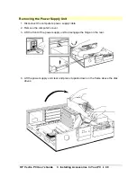
Page 40: ...ng the Power Supply Unit 1 Disconnect the computer s power supply cable 2 Remove the computer s cover 3 Lift the front of the power supply unit to disengage the hinge on the rear 4 Lift the power supply unit clear and place it upside down on the frame above the disk drives ...

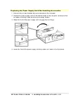
Page 41: ... installed all your accessories in the computer 2 Position the power supply unit over the left hand side of the computer and ensure that its cables are neatly routed around any accessory boards 3 Raise the front of the power supply unit to engage the rear hinge 4 Lower the front of the power supply unit into position so it rests on the front panel ...

Page 42: ...able in modules of 4 MB 8 MB 16 MB or 32 MB For a list of available modules refer to Supported HP Accessories The modules can be installed in any combination and any order WARNING Static electricity can damage electronic components Turn all equipment off Don t let your clothes touch the accessory To equalize the static electricity rest the accessory bag on top of the power supply unit while you ar...

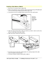
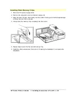
Page 43: ... remove an existing module to gain access to the vacant socket Release the retaining clip and pull the module forward and out of the socket 4 Align the module with the socket making sure that the end with a cutout is at the same end as A or B printed on the system board 5 Slide the memory module into the slot at 45 6 Pivot the memory module to the vertical position The retaining clips will click s...

Page 44: ...HP Vectra PC User s Guide 3 Installing Accessories In Your PC 44 8 Install any other accessories then refer to Checking the Installation to complete the installation ...

Page 45: ...increased performance you can install a memory module of 256 KB order D2465A WARNING Static electricity can damage electronic components Turn all equipment off Don t let your clothes touch the accessory To equalize the static electricity rest the accessory bag on top of the power supply unit while you are removing the accessory from the bag Handle the accessory as little as possible and with care ...

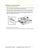
Page 46: ...atsink of the processor for better access to the cache module socket see diagram under Installing an Upgrade Processor Do not remove the processor 4 Align the cache memory module directly over the socket make sure that the cutout in the module is aligned with the bar in the socket Hold it upright with both hands and firmly push it straight down into position 5 Replace the heatsink on the processor...

Page 47: ...th be installed at the same time For a list of additional settings available once you have installed the extra memory see Available Video Resolutions WARNING Static electricity can damage electronic components Turn all equipment off Don t let your clothes touch the accessory To equalize the static electricity rest the accessory bag on top of the power supply unit while you are removing the accesso...

Page 48: ...ver and power supply unit 3 Align the video memory chip directly over the socket making sure that the tapered edge is facing the rear of the computer 4 Firmly press the memory chip completely into the socket 5 Repeat steps 3 and 4 for the second memory chip 6 Install any other accessories then refer to Checking the Installation to complete the installation ...

Page 49: ...Boards The PC has four accessory board slots Slot 1 the bottom slot can be used for half length 16 bit ISA boards Slot 2 can be used for full length 16 bit ISA boards Slot 3 can be used for full length 16 bit ISA or 32 bit PCI boards Slot 4 the top slot can be used for 32 bit PCI boards ...

Page 50: ...ry boards Your computer has support for Plug and Play in the BIOS Basic Input Output System To find out more about Plug and Play 1 Double click on the Plug and Play group icon in the Windows Program Manager 2 Double click on the ICU Notes icon for up to date information about the Plug and Play support for your PC NOTE PCI boards are configured automatically when installed in the PC ...

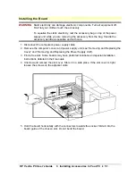
Page 51: ...le and with care 1 Disconnect the computer s power supply cable 2 Remove the computer s cover and power supply unit see Removing and Replacing the Cover and Removing and Replacing the Power Supply Unit 3 Find a free slot Some boards may have preferred locations and special installation instructions detailed in their manuals 4 Unscrew and remove the slot cover Store it in a safe place If the slot c...

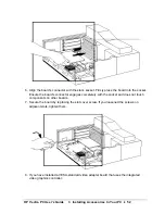
Page 52: ...to the socket Ensure the board s connector engages completely with the socket and does not touch components on other boards 7 Secure the board by replacing the slot cover screw If you loosened the screws on adjacent slots tighten them 8 If you have installed a VESA standard video adapter board that uses the integrated video graphics controller ...

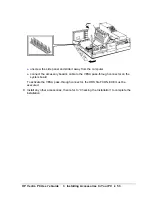
Page 53: ...it away from the computer connect the accessory board s cable to the VESA pass through connector on the system board To activate the VESA pass through connector the DOS file FCON EXE must be executed 9 Install any other accessories then refer to Checking the Installation to complete the installation ...

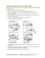
Page 54: ...will be available for an additional drive There is one front access drive shelf which may be used to install a flexible disk drive or a CD ROM drive Your PC has the following connectors on the system board that can be used by mass storage devices a flexible disk drive connector supporting up to two flexible disk drives two enhanced IDE drive connectors supporting up to three devices in total NOTE ...

Page 55: ... the middle shelf remove it Remember to remove its front panel screw and rear connectors 5 If there is no device in the middle shelf remove the cover plate 6 Remove the screw from the front panel Removing a device from the middle shelf step 4 Passing the device through the central shelf step 7 Removing the front panel screw step 6 Placing the device in the bottom shelf step 8 7 Pass the drive with...

Page 56: ...it one way only Data Connector for Hard Disk Drive 11 If a device was removed from the middle shelf replace it 12 If no device was removed from the middle shelf replace the cover plate 13 Return the hard disk drive in the rear shelf to its original position 14 Install any other accessories then refer to Checking the Installation to complete the installation ...

Page 57: ... computer s power supply cable 2 Remove the computer s cover see Removing and Replacing the Cover 3 Remove the cover plate and put it in a safe place 4 Slide the device with mounting rails attached into the middle shelf Step 4 Step 5 5 Secure the device in position using the screws provided with the device 6 Unscrew the hard disk drive in the rear shelf and rotate it out of the way for better acce...

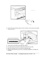
Page 58: ...y If you are installing a CD ROM drive refer to the manual supplied with the drive for detailed installation instructions Connector for 5 25 inch Device Connector for Flexible Disk Drive or CD ROM Data Cable Power Cable 8 Replace the hard disk drive in the rear shelf 9 Modify the cover so you can use the device in the middle shelf Turn the cover upside down Unclip the locking tab and lift the pane...

Page 59: ...HP Vectra PC User s Guide 3 Installing Accessories In Your PC 59 10 Install any other accessories before referring to Checking the Installation to complete the installation ...

Page 60: ...e operating system This utility is located in the HPutils group For non DOS Windows operating systems refer to the operating system documentation for information on creating a bootable diskette formatting a drive and installing the operating system 1 Disconnect the computer s power supply cable 2 Remove the computer s cover see Removing and Replacing the Cover 3 Place the drive with its label uppe...

Page 61: ...C 61 6 Connect the power cable and the data cable to the rear of the drive The connectors are shaped to go in one way only Data Cable Power Cable Data Connector 7 Install any other accessories then refer to Checking the Installation to complete the installation ...

Page 62: ...lacing the Power Supply Unit 3 Unclip the heatsink from the socket and remove the heatsink 4 Unlock the socket and lift out the old processor 5 To install the new processor a Locate the corner markers on the processor a dot or notch broken corner on the processor socket a dot b Position the processor over the socket with the processor s corner marker facing the socket s corner marker c Place the p...

Page 63: ...PC 63 details 7 Move processor type selection jumper JP8 to position 2 3 if you are installing a processor that does not support internal cache write back mode 8 Install any other accessories then refer to Checking the Installation to complete the installation ...

Page 64: ... computer can be used to secure the computer to your desk 1 Remove the computer s cover see Removing and Replacing the Cover 2 Insert the security bracket which you will find inside the computer into the slot shown in the diagram below 3 Press it firmly until it snaps into place 4 Install any other accessories before replacing the cover ...

Page 65: ...Processor 486DX2 66 MHz PASSED Memory cache 256KB PASSED Memory 8MB 640KB Base 384KB Reserved 7168 KB Extended PASSED Keyboard Mouse PASSED Flexible Disk Drives A 1 44 MB B 1 44 MB PASSED Parallel Ports PASSED Serial Ports 3F8h PASSED Hard disk Drives C 850MB D 270 MB PASSED System Configuration PASSED Setup F2 2 MB 66 Memory cache 256 KB 8MB B 1 44 MB D 270 MB Video Memory Processor Cache Memory ...

Page 66: ...cessories have been installed There are two methods of configuring your PC Use the Setup program when you have installed other accessories such as additional memory mass storage devices or accessory boards Use HP User Tools when you have installed additional video memory and are using Windows The following sections detail how to configure the PC for each accessory installed ...

Page 67: ... it is recommended that you use the Video Mode utility in HP User Tools to select settings see Using the HP User Tools For a list of additional settings available after installing extra video memory see Available Video Resolutions To enter the new settings 1 Select the resolution that you wish to change for example 800x600 and set the refresh rate required from the list provided Repeat for each re...

Page 68: ... Extended CHS as appropriate If you have installed an additional flexible disk drive and wish to use 1 2 MB capacity diskettes set the Flexible Drive 2field to 1 2 MB If you wish to use 1 2 MB capacity diskettes in the supplied drive set the Flexible Drive 1 field to 1 2 MB If you have no other changes to make press F3 to save the setting and exit the Setup program Printer or Plotter Select the mo...

Page 69: ...HP Vectra PC User s Guide 3 Installing Accessories In Your PC 69 2 If you have no other changes to make press F3 to save the setting and exit the Setup program ...

Page 70: ... extra video memory see Available Video Resolutions To enter the new settings 1 When Windows has loaded click on the HPutils group icon to display the Hewlett Packard utilities 2 Click on the HP User Tools icon to display the HP User Tools utility 3 Click on the Video Mode icon and follow the screen messages to change the video resolution and the number of colors displayed ...

Page 71: ...HP Vectra PC User s Guide 4 Troubleshooting 71 4 Troubleshooting ...

Page 72: ...HP Vectra PC User s Guide 4 Troubleshooting 72 The PC Does Not Work ...

Page 73: ...hooting 73 No Error Messages Displayed General Checks 1 All cables and power cables are firmly plugged in 2 The power outlet is working 3 The computer and display are turned on 4 The display s contrast and brightness settings are correct ...

Page 74: ...ard are properly set Refer to the manuals that came with each board If you have changed any jumpers on the system board check that they are properly set see System Board Jumpers and Connectors 5 Replace the cover see Replacing the Power Supply Unit After Installing Accessories 6 Connect all cables 7 Turn on the display and computer 8 If the PC still does not work Repeat steps 1 2 and 3 of this sec...

Page 75: ...HP Vectra PC User s Guide 4 Troubleshooting 75 Error Messages ...

Page 76: ... the HPROMInit utility Contact your dealer or your HP sales office for an HPROMInit utility diskette for the Vectra VE 4 xx To initialize the system ROM 1 Insert the HPROMInit utility diskette in drive A 2 Restart the PC and follow the instructions until the procedure finishes Do NOT switch off the PC until the ROM update procedure has completed successfully or not since irrecoverable damage to th...

Page 77: ... the next test by pressing ESC If an error appears when the PC starts Press F2 to run the Setup program and correct the System Configuration error see Using the HP Setup Program for information on using Setup Press F1 to continue and ignore the error It is recommended that you fix the error before proceeding even if the PC appears to start successfully Press F4 if you want to confirm that a device...

Page 78: ...dware was changed run Setup to update the configuration information 06xx The keyboard was pressed during the first step of the power on system hardware test Ensure that nothing is pushing down on the keyboard and that no key is stuck down If the problem persists contact your service representative 61xx 6500 6510 6520 8x06 Ensure the memory modules are installed correctly see Installing Memory If t...

Page 79: ...ed Press any key to try again You tried to start the PC but the PC could not find the operating system Check that the flexible disk contains the operating system Check that the hard disk drive contains the operating system Ensure Start from FDD or Start from HDD is enabled in the Setup program Non system disk or disk error Remove the diskette or replace it with the proper operating system diskette...

Page 80: ...HP Vectra PC User s Guide 4 Troubleshooting 80 Hardware Problems This section describes what to do if you have problems with your display disk drives printer accessory board keyboard or mouse ...

Page 81: ... are bent If they are carefully straighten them Check that an accessory board does not use the same I O address as the integrated video interface 03B0h to 03DFh Refer to the documentation supplied with the accessory for more information 2 If the display image does not align with the screen usually when you change resolutions use the display s controls to center the image Refer to the display manua...

Page 82: ...ay the MS DOS startup menu 3 When the MS DOS startup menu appears press F5 to display the MS DOS prompt C 4 Type CD C WINDOWSand press ENTER 5 Type SETUP and press ENTER 6 Use the arrow key to select the Display line and press ENTER 7 Select the VGA line and press ENTER 8 Press ENTER again to accept the configuration 9 Press CTRL ALT and DELETE to restart the PC 10 If necessary type WIN ENTER to r...

Page 83: ...Connectors and Jumpers for the jumper location 3 Switch on the PC to erase the memory 4 Check that the message Configuration has been cleared in English is displayed and allow the PC to complete it s startup routine 5 Switch off the PC 6 Return the system board jumper JP5 to position 1 2 to re enable the configuration 7 Replace the cover see Removing and Replacing the Cover 8 Switch on the PC and ...

Page 84: ...eck that the keyboard or mouse is correctly connected see Connecting the Mouse Keyboard and Display 2 Check that the mouse driver supplied with the preloaded software is installed correctly Choose a Logitech mouse driver in Windows Setup 3 Clean the mouse ball as shown in the figure below ...

Page 85: ...onfigured correctly for the PC and for the application a Check that the PC s port has been correctly configured using the Setup program b Check that the printer is correctly set up in Windows NOTE If you are asked to insert a diskette when installing a printer type C WINDOWS OPTIONSand press ENTER All of the Windows printer drivers are located in this subdirectory c Ensure the application program ...

Page 86: ...ou are using a diskette that is the right density 3 Check that the flexible disk drive has not been disabled in the Setup program see Setting Other Security Features 4 Check that the disk power and data cables are correctly connected see Installing a Flexible Drive or a CD ROM Drive in the Middle Shelf 5 Clean the flexible disk drive using a wet cleaning diskette kit ...

Page 87: ... that the disk power and data cables are correctly connected see Installing or Replacing an IDE Hard Disk Drive in the Rear Shelf 3 Check that power management has been correctly configured see Using Power Management 4 Check that the IDE Interface has not been disabled in the Setup program 5 Check that the Translation Method and Data Transfer Method are correctly specified in theSetup program ...

Page 88: ... that the control panel connector is firmly attached to the system board 2 Check that the disk power and data cables are correctly connected to the drive see Installing or Replacing an IDE Hard Disk Drive in the Rear Shelf 3 If you are using a hard disk drive with a controller board for example a SCSI hard disk the activity light does not flicker when the PC is accessing the hard disk drive ...

Page 89: ...correctly configured with the ISA Configuration Utility ICU See Installing Accessory Boards 3 Ensure the board is not using memory I O addresses an IRQ or DMA channel also used by the PC Refer to the board s manual for details See also IRQs DMAs and I O Addresses Used 4 Check that the PC has been configured correctly in the Setup program 5 If the problem persists contact your service representativ...

Page 90: ...4 Troubleshooting 90 You Lose the Key If you lose the key to the PC you need to order a replacement lock HP part number 5062 5590 from your HP dealer or HP Sales and Service Office To install the new lock contact your HP dealer ...

Page 91: ...NING Remove the old battery before installing the replacement battery Always install the battery in the correct position as indicated There is a danger of explosion if the battery is incorrectly replaced For your safety and to protect the environment never attempt to recharge disassemble burn or throw away the old battery Dispose of used batteries according to the manufacturer s instructions Addit...

Page 92: ...ve the existing battery and firmly press down the battery holder 3 Connect the external battery cable to the battery connector on the system board as shown below Battery Holder 4 Mount the external battery on the backplane using the self adhesive strip supplied 5 Replace the cover see Removing and Replacing the Cover 6 Run the PC s Setup program to reconfigure the computer ...

Page 93: ...the existing battery by lifting the battery holder and sliding out the battery 3 Push the battery holder down when the battery socket is empty 4 Insert the new battery 5 Check that the battery is held firmly in place by the battery holder otherwise return to step 2 6 Replace the cover see Removing and Replacing the Cover 7 Run the PC s Setup program to reconfigure the computer ...

Page 94: ...HP Vectra PC User s Guide 4 Troubleshooting 94 Software Problems ...

Page 95: ... to change the system configuration settings including User password in the Setup program To reset the Administrator password 1 Switch off the PC and remove the computer s cover see Removing and Replacing the Cover 2 Move the JP5 jumper on the system board to position 2 3 see System Board Connectors and Jumpers for the jumper location 3 Switch on the PC and check that the message Configuration has...

Page 96: ...e PC to erase the memory 4 Switch on the PC and check that the message Configuration has been cleared in English is displayed and allow the PC to complete it s startup routine 5 Switch off the PC 6 Return the system board jumper JP5 to position 1 2 7 Replace the cover see Removing and Replacing the Cover 8 Switch on the PC and check that the error codes 0241 0280 and 0130 are displayed indicating ...

Page 97: ...are Does Not Work If the PC reports the system is OK but an application won t run 1 Check to see if the AUTOEXEC BATfile is present with the correct settings Refer to the operating system manuals 2 If Windows does not run properly refer to the Windows manual for guidance ...

Page 98: ...HP Vectra PC User s Guide 4 Troubleshooting 98 Power Management Does Not Work ...

Page 99: ...t is enabled using the Power icon in the Windows Control Panel 1 Double click on the Power icon in the Windows Control Panel 2 Check that Advancedis selected in the Power dialog box If the Power icon does not appear in the Windows Control Panel 1 At the MS DOS prompt change to the C WINDOWSdirectory 2 Run Windows Setup and set the Computerfield to MS DOS with APM ...

Page 100: ...HP Vectra PC User s Guide 4 Troubleshooting 100 Power Management in DOS Use a text editor to check that DEVICE C DOS POWER EXE ADV MAX is present in the CONFIG SYSfile ...

Page 101: ...s the daylight saving hour changes the PC has been unplugged from the power too long and the battery is discharged To change the date and time use the HP User Tools program See Using the HP User Tools for more information about the HP User Tools If the problem persists replace the battery as described under You Need to Replace the Battery ...

Page 102: ...HP Vectra PC User s Guide 5 Technical Information 102 5 Technical Information ...

Page 103: ...HP Vectra PC User s Guide 5 Technical Information 103 Specifications ...

Page 104: ... IRQ 7 option 3 3BCh IRQ 7 or Off 9 pin serial connectors Standard Two UART 16550 buffered serial ports both RS 232 C Serial port Serial Port A 3F8h IRQ 4 3E8h IRQ 4 or Off Serial Port B 2F8h IRQ 3 2E8h IRQ 3 or Off System board connectors VESA internal video pass through connector One flexible disk drive connector allows 2 drives Two enhanced IDE connectors allows 2 IDE hard disk drives and 1 CD ...

Page 105: ...F Storage humidity 8 to 80 relative Operating temperature 5 C to 40 C 41 F to 104 F Operating humidity 15 to 80 relative Maximum thermal dissipation 91 kcal per hour 360 BTU per hour Acoustic noise emission 39 db in the workplace under normal conditions as defined by DIN 45635 T 19 and ISO 7779 Power supply Input voltage 100 127 Vac 200 240 Vac auto ranging Input frequency 50 60 Hz Maximum power 1...

Page 106: ... button on the front panel the power consumption falls below 5 watts but is not zero This special on off method used by this PC considerably extends the lifetime of the battery To reach zero power consumption in off mode either unplug the PC from the power outlet or use a power block with a switch You should be aware that in this case the PC will lose its time settings within a few days ...

Page 107: ...rive controller IRQ15 available for integrated PCI devices if not used by an ISA board DMAs used by PC DMA 0 free DMA 1 free if not used for parallel port in Setup DMA 2 flexible disk drive controller DMA 3 free if not used for parallel port in Setup DMA 4 used to cascade DMA channels 0 3 DMA 5 free DMA 6 free DMA 7 free I O addresses used by PC 1F0h 1F7h integrated IDE hard disk controller 278h 2...

Page 108: ...HP Vectra PC User s Guide 5 Technical Information 108 For information on current usage of IRQs DMAs and I O addresses by your PC type MSD at the MS DOS prompt ...

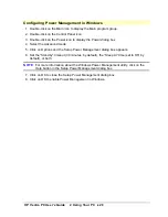
Page 109: ...Information 109 Error Bookmark not defined Available Video Resolutions Windows 3 11 video drivers are preloaded on your system OS 2 and Windows NT video drivers can obtained through the HP Bulletin Board System BBS Library or your HP dealer ...

Page 110: ...following video settings are available Resolution No of Colors Refresh Rates 640 x 480 256 32 K 64 K 60 72 75 Hz 800 x 600 256 32 K 64 K 56 Hz 256 colors only 60 72 75 Hz 1024 x 768 256 43i interlaced 60 70 75 Hz 1280 x 1024 16 45i interlaced 60 72 75 Hz Not available for Windows NT or OS 2 ...

Page 111: ...eo settings are possible once the video memory has been upgraded to 2 MB Resolution No of Colors Refresh Rates 640 x 480 16 M 60 72 75 Hz 800 x 600 16 M 60 72 75 Hz 1024 x 768 32 K 64 K 43i interlaced 60 70 75 Hz 1280 x 1024 256 45i interlaced 60 72 75 Hz 16 7M for Windows NT and OS 2 Not available for Windows NT or OS 2 Not available for OS 2 ...

Page 112: ... 960 KB to 1024 KB 0F0000 to 010000 64 KB BIOS area 896 KB to 960 KB 0E0000 to 0F0000 64 KB available 800 KB to 896 KB 0C8000 to 0E0000 96 KB available for accessory boards 768 KB to 800 KB 0C0000 to 0C8000 32 KB video BIOS area 640 KB to 786 KB 0A0000 to 0C0000 128 KB video memory area 640 KB Base Memory Area 0 KB to 640 KB 09F000 to 0A0000 Extended BIOS data area User application program area MS...

Page 113: ...HP Vectra PC User s Guide 5 Technical Information 113 Rear Connectors Keyboard Mouse Connectors Serial Connector Parallel Connector VGA Video Connector ...

Page 114: ...onnector System Board Jumpers Jumper Name Setting Function JP5 1 2 2 3 CMOS Operation Normal default Clear CMOS JP818 1 2 2 3 Processor Type cache mode selection Internal cache write back mode Internal cache write through mode JP13 1 2 2 3 Processor Speed 33 MHz 25 MHz Setting dependent on model 1Setting dependent on model ...

Page 115: ...seful life HP has a take back program in several countries The collected equipment is sent to one of HP s recycling facilities in Europe or the U S A As many parts as possible are reused the remainder is recycled Special care is taken with batteries and other potentially toxic substances which are reduced into non harmful components through a special chemical process If you require more details ab...

Page 116: ...HP Vectra PC User s Guide 6 Getting Support 116 6 Getting Support ...

Page 117: ...r questions regarding non HP hardware software systems or usage not intended for or not commonly used with the HP Vectra contact your Authorized HP Reseller For questions regarding product development or custom installations we suggest that you contact your Authorized HP Reseller third party support services or the HP Customer Support organization in your country They will be able to offer you con...

Page 118: ...eller This easy and comprehensive support plan includes the HP SupportPack hotline to solve your problems over the phone and if needed provide fast and convenient next day on site repair of your HP Vectra PC HP SupportPack is backed by Hewlett Packard s technical resources and must be purchased from your local reseller within 30 days of your HP Vectra purchase ...

Page 119: ...14400 Worldwide 1 208 344 1691 300 1200 2400 4800 9600 14400 Set your modem for no parity 8 data bits and 1 stop bit N 8 1 HP FAXback on Demand HP FIRST You can use this service to select documents such as product descriptions and technical information which are then faxed to you To access this service use the handset on your fax machine and dial Country Number United States 1 800 333 1917 Worldwi...

Page 120: ...ffers drivers and information on HP products This library service is available to anyone in the world who has FTP access to the Internet or World Wide Web access through a hyper media viewer Internet IP Address Alias 192 6 71 2 ftp boi external hp com Name Password anonymous Enter your E mail address World Wide Web URL http www hp com home html ...

Page 121: ...ited Kingdom simply call the number shown below and ask for representative 51 For all other locations you should first call the Worldwide number to obtain the number of your local sales office then call your local sales office and ask for representative 51 Country Local Call Freephone number Direct number United States 1 800 848 8199 1 614 529 1349 United Kingdom 0800 289378 44 1272 760680 Worldwi...

Page 122: ...s used For more detailed information about your system configuration contact your Authorized HP Reseller HP North American Customer Support Center Assistance from the HP North American Customer Support Center is available Monday to Friday 7 00 AM to 6 PM Mountain time except Wednesday when the hours are 7 00 AM to 4 PM The number is 1 303 635 1000 HP European Customer Support Center Assistance fro...

Page 123: ...Packard S A 150 route du Nant d Avril P O Box 1217 Meyrin 2 Geneva Switzerland USA Intercon Operations Hdqtrs Hewlett Packard Company 3495 Deer Creek Road P O Box 10495 Palo Alto CA 94303 0896 USA MIDDLE EAST AFRICA Middle East Central Africa Sales Hdqtrs Hewlett Packard S A Rue de Veyrot 39 CH 1217 Meyrin 1 Geneva Switzerland CANADA Hewlett Packard Ltd 6877 Goreway Drive Mississauga Ontario L4V 1...

Page 124: ...HP Vectra PC User s Guide Glossary 124 Glossary ...

Page 125: ... the computer CMOS memory stores information that must be maintained such as your computer s configuration controller A device that enables another device to communicate with the computer device driver Software that enables the computer to interface with a specific peripheral such as a printer extended memory Any memory with an address higher than 1 MB HP Utilities Software provided by Hewlett Pac...

Page 126: ...is running as an unattended network server pixel Picture element The smallest addressable spot on the screen POST Power On System Hardware Test A series of tests your computer performs when you turn on the power RAM Random Access Memory Computer memory used to temporarily hold programs and data resolution How fine the detail is on a screen or printout Screen resolution is measured in pixels across...

Page 127: ...n line Memory Module A board containing several RAM chips See memory modules system board The large circuit board onto which all other boards are plugged video controller An board or chip whose function is to convert signals in the computer into displayable signals video RAM Memory that enables or speeds up drawing to the screen or increases resolution or color options ...

Page 128: ...HP Vectra PC User s Guide 7 Regulatory Information and Warranty 128 7 Regulatory Information and Warranty ...

Page 129: ...ms to the following Product Specifications SAFETY International IEC 950 1991 A1 A2 Europe EN 60950 1992 A1 A2 EMC International CISPR 22 1985 Class B Europe EN 55022 1988 Class B EN 50082 1 1992 prEN 55024 2 1992 IEC 801 2 1992 3 kV CD 8 kV AD prEN 55024 3 1991 IEC 801 3 1984 3 V m prEN 55024 4 1992 IEC 801 4 1988 0 5 kV Signal Lines 1 kV Power Lines Supplementary information The product complies ...

Page 130: ...rference will not occur in a particular installation If this equipment does cause harmful interference to radio or television reception which can be determined by turning the equipment off and on the user is encouraged to correct the interference by one or more of the following measures reorient or relocate the receiving antenna increase the separation between the equipment and the receiver connec...

Page 131: ...rranty 131 Notice for Canada This Class B digital apparatus meets all requirements of the Canadian Interference Causing Equipment Regulations Cet appareil numérique de la Class B respecte toutes les exigences du Règlement sur le matériel brouilleur du Canada ...

Page 132: ... cord according to your local national electric code USA use a UL listed type SVT detachable power cord Canada use a CSA certified detachable power cord Si le cordon secteur n est pas livré avec votre ordinateur utiliser un cordon secteur en accord avec votre code electrique national USA utiliser un cordon secteur UL list de type SVT Canada utiliser un cordon secteur certifié CSA ...

Page 133: ...7 Regulatory Information and Warranty 133 Notice for the United Kingdom The HP Vectra PC is approved under approval number NS G 1234 J 100003 for indirect connection to Public Telecommunication Systems within the United Kingdom ...

Page 134: ... PC User s Guide 7 Regulatory Information and Warranty 134 Noise Declaration for Germany Lärmangabe nach Maschinenlärmverordnung 3 GSGV Deutschland LpA 70 db am Arbeitsplatz normaler Betrieb nach EN 27779 11 91 ...

Page 135: ...HP Vectra PC User s Guide 7 Regulatory Information and Warranty 135 Notice for Japan ...

Page 136: ...HP Vectra PC User s Guide 7 Regulatory Information and Warranty 136 Notice for Korea ...

Page 137: ...ication operation or storage outside the environmental specifications for the product in transit damage improper maintenance or defects resulting from use of non HP software accessories media supplies consumables or such items not designed for use with the product HP makes no other express warranty whether written or oral with respect to this product Any implied warranty of merchantability or fitn...

Page 138: ... In this event HP will prepay shipping charges duty and taxes provide telephone assistance on replacement of the component and pay shipping charges duty and taxes for any part that HP asks to be returned HP products external to the system processor unit such as external storage subsystems displays printers and other peripherals are covered by the applicable warranties for those products HP softwar...

Page 139: ...r return of products to the customer except for products returned to the customer from another country HP Software Product License Agreement and Software Product Limited Warranty CAREFULLY READ THIS LICENSE AGREEMENT BEFORE PROCEEDING TO OPERATE THIS EQUIPMENT RIGHTS IN THE SOFTWARE ARE OFFERED ONLY ON THE CONDITION THAT THE CUSTOMER AGREES TO ALL TERMS AND CONDITIONS OF THE LICENSE AGREEMENT PROC...

Page 140: ...r any copy or adaptation in violation of the U S Export Administration regulations or other applicable regulation 9 GOVERNMENT RESTRICTED RIGHTS Use duplication or disclosure by the U S Government is subject to restrictions as set forth in subparagraph c 1 ii of the Rights in Technical Data and Computer Software clause in DFARS 252 227 7013 Hewlett Packard Company 3000 Hanover Street Palo Alto CA ...

Page 141: ...exclusion may not apply to you This warranty gives specific legal rights and you may also have other rights which vary from state to state or province to province Limitation of Liability and Remedies THE REMEDIES PROVIDED ABOVE ARE CUSTOMER S SOLE AND EXCLUSIVE REMEDIES IN NO EVENT SHALL HP BE LIABLE FOR ANY DIRECT INDIRECT SPECIAL INCIDENTAL OR CONSEQUENTIAL DAMAGES INCLUDING LOST PROFIT WHETHER ...

Reviews: