background image

Pneumatic system | 7

60013444 • 01 • 01/2021 • en

73

Deposits on the protective grid restrict the air flow and thus lead to blockage in the
hoses.

Ø

Clean the protective suction grid at regular intervals to prevent a restriction in
air flow and resulting blockage.

Deposits on the fan impeller cause unbalance. The bearing will thereby be over-
loaded and can be damaged.

Ø

Clean any dirt or deposits from the fan blades to prevent unbalance and dam-
age to impeller and bearing.

The hydraulic oil could overheat if the radiator fins are soiled and cause clogging of
the fertiliser hoses.

Ø

Clean the radiator fins at regular intervals.

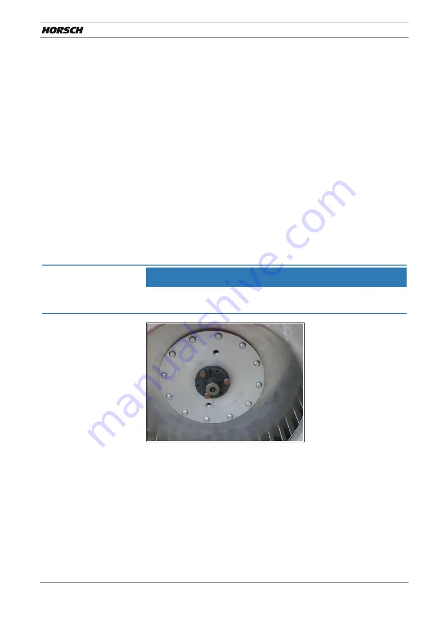
7.6.1 Retightening the fan flange

The clamping taper fixates the fan wheel and additionally clamps on the drive shaft.

The clamping taper on the fan drive may come loose. The impeller can thus move
along the drive shaft and damage the fan.

NOTE

After approx. 50 hours retighten the clamping taper on the fan flange and check it
annually.

Clamping taper

When tightening the screws, especially with a new assembly, the fan wheel will
move towards the housing in the direction of the protective grid.

1. Align a loose flange closer to the hydraulic motor, the gap between impeller

and intake side must remain as small as possible.

2. Clean the clamping faces from oil and grease.

3. The clamping screws must be tightened uniformly and in several steps. Use a

plastic hammer or hammer shaft in between to carefully knock on the flange
to facilitate pulling onto the cone.

4. The inch screws in versions no. 10-24 4.6 may be tightened with a torque of

max. 6.8 Nm.

5. After tightening check the impeller for free and even running.

Summary of Contents for Maestro CX

Page 1: ...OPERATING INSTRUCTIONS Maestro CX 60013444 01 01 2021 en TRANSLATION OF THE ORIGINAL OPERATING INSTRUCTIONS READ CAREFULLY PRIOR TO STARTING UP KEEP OPERATING INSTRUCTIONS IN A SAFE PLACE...

Page 2: ......

Page 3: ...ystem 14 2 6 6 Propshaft PTO shaft 15 2 6 7 Overhead lines 15 2 6 8 Technical limiting values 16 2 6 9 Use in the field 16 2 7 Changing equipment wear items 16 2 8 Fertiliser and dressed seed 17 2 9 E...

Page 4: ...7 4 2 Fan speeds 69 7 4 3 Fertiliser quantities 70 7 5 Drive with PTO shaft pump 70 7 6 Checks and maintenance 72 7 6 1 Retightening the fan flange 73 7 6 2 Troubleshooting 74 7 7 Central distributor...

Page 5: ...ger 143 14 4 Agitator shaft 146 14 5 AutoForce 147 14 6 Fertiliser flow monitoring 147 14 7 Bout marker 148 15 Troubleshooting 150 16 Care and maintenance 153 16 1 Maintenance overview 153 16 1 1 Afte...

Page 6: ...s Winkler Dokumentationsbevollm chtigter Philipp Horsch Gesch ftsf hrer Hubertus Bultmann Leiter Forschung Entwicklung Translation of EC Declaration of Conformity The manufacturer HORSCH Maschinen Gmb...

Page 7: ...of machine Please enter the corresponding data into the following list upon reception of the machine Serial number Machine type Year of construction Initial use Accessories Dealer address Name Road Pl...

Page 8: ...ive and regular maintenance and inspection Transport Trained personnel of our service and sales partners will provide orientation on how to operate and maintain the machine By submitting the acknowled...

Page 9: ...ant notes Instructions for actions and their elements are marked by different symbols Prerequisites for instructions for actions 1 Instructions for actions alternative and in warning notes arrow tips...

Page 10: ...s of application When participating with the machine in public road traffic the respective national registration and traffic law must also be complied with Any other kind of use of the machine contrad...

Page 11: ...able road traffic regulations and is in possession of a valid driving permit for road travel A person being instructed must only work with or on the machine under the supervision of an experienced per...

Page 12: ...ention to permissible transport widths and heights Pay attention to the transport height when passing under bridges and low hanging overhead power lines Do not exceed the permissible axle load tyre lo...

Page 13: ...tective features and safety equipment such as detachable protective devices wheel chocks etc must be correctly in place and reliably functioning before the machine is put into operation Check nuts and...

Page 14: ...system Depressurise the hydraulics on the tractor and implement side The hydraulic system is under high pressure Check all lines hoses and screwed connections regularly for leaks and any visible exte...

Page 15: ...actor engine pull off the ignition key and wait until all parts have come to a standstill Follow the operating instructions for the propshaft 2 6 7 Overhead lines When unfolding or folding in the wing...

Page 16: ...ondition of the cultivation tools and their mounting before use Driving stability may be affected in the following situations especially when cornering Driving at accelerated speed along the contour l...

Page 17: ...nvironment Pick up drained operating materials with absorbent material or sand fill it into a leak tight tank and dispose of in accordance with statutory regulations 2 10 Retrofitting and conversions...

Page 18: ...t rolling away Depressurise the hydraulic system and lower or support the implement Prior to working on the electrical system disconnect it from the electric cur rent supply When performing welding wo...

Page 19: ...er slowly and unnoticed Failing to pay attention to the danger zone can result in severe or even fatal physical injuries 1 Do not stand under lifted loads Lower such loads to the ground first 2 Instru...

Page 20: ...ety stickers 2 Damaged or illegible safety stickers must be replaced immediately 3 Affix the specified safety stickers on spare parts 00380054 No passengers are allowed to ride on the machine 00380055...

Page 21: ...uger 00380294 Shut the engine down and pull off the key before starting maintenance and repair work 00380299 Do not climb on rotatable parts Use mounting steps provided for this purpose 00380894 In or...

Page 22: ...35 The pressure accumulator is charged with gas or oil pres sure Dismantle and repair only in strict compliance with the instructions in the technical manual 2 14 1 Positions of safety stickers The po...

Page 23: ...a tractor or needs to be lifted off with suitable lifting gear forklift truck or crane Use only lifting equipment and lifting gear with adequate lifting capacity and approval Points with the associat...

Page 24: ...he machine will be carried out by our service engineers or distributors Any preceding use of the machine is prohibited The machine can only be released for operation after the instruction session cond...

Page 25: ...4 01 01 2021 en 25 3 3 1 Adapting the seed bar The incline of the seed bar depends on the connecting height of the machine on the tractor It must therefore be adapted accordingly see Chapter Operation...

Page 26: ...x 2 30 0 7 x 2 30 0 7 x 2 30 Seed hopper capacity l 70 70 70 Hopper capacity mi cro granulate facility l 300 300 300 Number of rows 8 9 12 Coulter pressure hy draulic kg 150 350 150 350 150 350 Depth...

Page 27: ...pends on the equipment specification with minimum equipment The permissible transport heights and transport width for road traffic may differ from country to country Comply with the national registrat...

Page 28: ...4 Technical data 28 60013444 01 01 2021 en Maestro 9 CX 5550 6610 5900 2960 3920 2960 9 70 CX 7590 I 9 75 CX 7160 I 9 80 CX 7590...

Page 29: ...Technical data 4 60013444 01 01 2021 en 29 Maestro 12 CX 5550 6390 5900 2990 3890 2960 6790...

Page 30: ...r 6 Vehicle identification number VIN 7 Technically permissible total weight 8 permissible drawbar load 9 Technically permissible axle load axles 1 2 3 Information on year of manufacture Year of manuf...

Page 31: ...ctions of the tractor Verify the suitability of the tractor before commissioning The tractor must meet the following requirements to be able to use the machine as intended Implement attachment Maestro...

Page 32: ...able flow rate 1 hydraulic filling auger single hopper Pressureless return flow for hydraulic fan direct drive fertiliser and Overpressure max 5 bar 1 Oil quantity hydraulic fan overpressure without M...

Page 33: ...ctor GH Total weight of rear implement In case of towed machines Maximum permissible drawbar load for road transport GV Total weight of front implement front ballast a Distance from front implement fr...

Page 34: ...calculated actual front axle load and the permissible front axle load from the operating instructions of the tractor into the table 4 Calculation of the actual total weight Enter the result of the ca...

Page 35: ...nd rear axle load minimum front axle load 20 of the tractor s curb weight The calculated values must not exceed the permissible values Actual value as calculated Permissible value from operating instr...

Page 36: ...rt 3 Radar sensor 4 Fan 5 Wheel chocks 6 Exhaust air hose 7 Lift Lower hydraulic cylinders 8 Undercarriage 9 Fertiliser feeder 10 Drill unit 11 Fertiliser distributor tower 12 Seed hopper 13 Fertilise...

Page 37: ...equipment sides NOTE Operate the machine with mineral based hydraulic oil Do not mix mineral oils with organic or ester oils The hydraulic circulation of the tractor must contain mineral based hydrau...

Page 38: ...444 01 01 2021 en Hydraulic valve block Fan fertiliser Auger Pressureless return CAUTION Damages on the hydraulic motor The return flow pressure on the fan drive must not exceed 5 bar Hydraulische_Bre...

Page 39: ...black Silver Thickness 7 mm 10 mm 19 mm 30 mm 50 mm WARNING Risk of injury on the hydraulic cylinders Limbs may be pinched or crushed by unintentional retraction of the piston rods Park the machine t...

Page 40: ...pin plug B Rear light right B 1 Lamp blinker B 2 Lamp tail light B 3 Lamp brake light C Rear light left C 1 Lamp brake light C 2 Lamp tail light C 3 Lamp blinker Number Designation Colour Function 1...

Page 41: ...on stickers 1 Clean soiled stickers 2 Damaged or illegible stickers must be replaced immediately 3 Apply the specified stickers to spare parts 00385630 Check the tyre pressure at regular inter vals ad...

Page 42: ...44 01 01 2021 en 00380879 Attach the scales here when calibrating 00385214 Preload the folding hydraulics with min 100 bar in the field 00386222 Display for coulter pressure 00384068 00384068 Pressure...

Page 43: ...for fertiliser feeder coulter pres sure 00386224 Tightening torque for parallelogram con sole 00385488 300 00385488 Tighten with the appropriate torque 00385489 510 00385489 Tighten with the appropria...

Page 44: ...atic system to avoid leaks Leaks will cause sowing faults Air losses reduce the placing quantity which could even drop to zero 00386220 Display for MTS System Main Tank Sup ply System 00380374 Tank fi...

Page 45: ...Attachment 5 60013444 01 01 2021 en 45 1 2 00385661 Filling auger 1 Activating 2 Deactivating 60008263 Display for overpressure...

Page 46: ...es the machine or moves away from it WARNING Leaking hydraulic fluid can cause serious injuries Danger of injury by unwanted machine movements Connect and disconnect the hydraulic lines only when the...

Page 47: ...e to clear Machines with ball and socket coupling Release the hold down Raise the drawbar by cranking on the support until the ball has cleared Machines with tractor link arm Engage the machine Insert...

Page 48: ...coupling connection follow the notes in the maintenance overview chapter When using a drawbar eye connection follow the notes in the maintenance overview chapter NOTE Make sure before driving on publi...

Page 49: ...lways be disconnected first DANGER With negative drawbar load the machine may tilt back and cause severe injury to persons Park the machine never with raised seed bar 1st option Parking the machine in...

Page 50: ...ownward slope 5 Direct the bottom plate on the support downward Secure the pin with the cotter pin 6 Crank down the support 7 Unplug the brake lines ISOBUS and lighting and hook in the bracket Attach...

Page 51: ...machine Machines with drawbar eye Adjust the height of the drawbar by cranking the support so that the machine can be picked up Engage the machine Insert the bolts and secure them Machines with ball a...

Page 52: ...i theft devices The anti theft devices protect the machine against unauthorised use The securing devices are attached to the hitch or drawbar eye and secured with a lock Securing device for ball coupl...

Page 53: ...in an inclined position when folding it Fold the machine only on a level and firm surface WARNING With negative drawbar load the machine may tilt back and cause severe injury to persons When folding...

Page 54: ...hem to the stop 6 Check the pre tensioning pressure for the folding cylinders on the pressure gauge minimum pressure 100 bar 7 Press the softkey Lower seed bar to completely lower the seed bar 8 Conti...

Page 55: ...s and fold the outer joints by hand 2 Insert the bolts and secure with the cotter pin 1 3 Turn on the drill controls 4 In the Folding in menu activate the softkey Lift fold 5 Operate the control unit...

Page 56: ...on before road travel see Transport position 6 3 Seed bar adjustment The machine must be adjusted to the tractor and the soil conditions to allow ad equate space for movement The seed bar is set corre...

Page 57: ...g 3 1 2 1 Lift the machine 2 Loosen the locking nuts 1 with hammer blows and turn them back fully 3 Lower the machine to relieve the upper link spindles 4 Adjust the inside nuts 2 with the integrated...

Page 58: ...The more clips are put in place the higher the seed bar is positioned 1 Lift the seed bar 2 Place the same number of clips on the piston rods of both hydraulic cylinders 1 1 3 Lower the seed bar and...

Page 59: ...r Activate the drill controls Follow the associated operating instructions for the settings on the drill controls Perform the calibration for fertiliser metering see chapter Pneumatic system fertilise...

Page 60: ...niformly and moderately during entering Metering delay When starting to use the machine the grains from the individual metering units drop directly on the field Fertiliser needs approx 1 2 seconds lon...

Page 61: ...n the adjustments and checks made prior to and during use as well as on regular care and maintenance of the machine Carry out all maintenance tasks and adjustments before starting to work NOTE Check t...

Page 62: ...ed and are they still serviceable In case of small seed has the cleaning brush been installed and is it in order In the case of large seed has the scraper been installed Are all connections airtight a...

Page 63: ...il port of the tractor Note the return flow pressure of max 2 bar of the leak oil line Depending on the equipment version the pneumatic system consists of Tank Overpressure system with fan for single...

Page 64: ...both fans Overpressure level for metering units in mbar Variant with MTS 1 2 3 4 5 6 7 8 10 13 14 9 12 11 1 Seed fertiliser fan 8 Distributor tower for micro granular compound 2 Throttle valve micro...

Page 65: ...atforms 2 Fold the steps back up after leaving the platforms Engage the step on the drawbar NOTE In case of extreme dust development this dust may deposit in the fertiliser hopper and fill up the roll...

Page 66: ...opper lid securely with the levers before each use in the field NOTE During transportation over long distances or on very bumpy roads the fertiliser in side hopper may solidify Before starting work th...

Page 67: ...ressure The hydraulic fan for overpressure generation is directly driven by the tractor hy draulics or by a PTO shaft pump option For direct drive the tractor must be equipped with a flow control valv...

Page 68: ...the cleaning covers on the frame and clean frame and hoses see chapter Care and maintenance NOTE Damaged or pinched hoses or defective connections must be immediately re placed or repaired 7 4 Fertili...

Page 69: ...rpm Maestro CX 4 000 4 500 Table 1 Reference values of fan speeds at 10 km h NOTE The optimal rotational speed must be determined by field tests or during a test placement The guide values must only b...

Page 70: ...reliably fastened anti twist lock WARNING Risk of accident The parking position on the drawbar must only be used with the machine shut down For road travel or in the field the pump should always be m...

Page 71: ...ow raise the PTO shaft speed again by approx 10 Function The two PTO shaft pumps power the hydraulic motors for the fans The flow control valves 1 2 are used to regulate the oil flow and thus the fan...

Page 72: ...ntamination 5 Replace return filter annually 6 Change the oil as necessary 7 Retighten the clamping tapers on the fan shafts see chapter Fan Flange NOTE The radiator fins must be cleaned at regular in...

Page 73: ...mps on the drive shaft The clamping taper on the fan drive may come loose The impeller can thus move along the drive shaft and damage the fan NOTE After approx 50 hours retighten the clamping taper on...

Page 74: ...ed Protective fan grid soiled Oil cooler dirty PTO shaft speed too high Reduce power and check oil level Check pressure on fan Change oil and oil filter Clean protective fan grid Clean radiator fins A...

Page 75: ...tions 2 Check the set air pressure on the pressure gauge 4 The value in the pressure gauge thereby fluctuates around a mean value 3 Recommended values depending on the Thousand Seed Weight and grain s...

Page 76: ...sensors Checks and maintenance Error messages in the drill controls may be caused by air losses in the MTS System or in the Overpressure range 1 Check all hoses and connections every day for leaktight...

Page 77: ...System or in the Closing the outlets If individual rows are no supplied with seed the outlets can be closed with blind plugs 1 Loosen the bayonet lock on the connection and remove the hose 2 Plug in...

Page 78: ...he drill controls 1 Hoses and distributors must therefore be checked and cleaned daily depend ing on deposits also in between 2 For this reason take off the distributor cover and remove any deposits w...

Page 79: ...k when making changes to settings and when working on larger areas also regularly in between The individual drill units of the Maestro are flanged to a foldable transverse frame All assembly groups fo...

Page 80: ...the hopper is open dust and dirt may fall in This increases wear and results in metering errors Foreign objects can block or destroy the metering unit Dressing dust could escape or seed may drop out d...

Page 81: ...causes malfunctions on the sensors 1 Open all seed hoppers and fill them uniformly 2 Close the seed hopper and secure them with the snap locks Leak tightness NOTE Metering errors from leaks on the se...

Page 82: ...pre tension will reduce due to wear and the discs will no longer have contact In this case the discs must be replaced or readjusted 1 2 3 Coulter disc adjustment 1 Unscrew the depth guide wheels See t...

Page 83: ...craping the insides of the coulter discs Protect the Barrel from damages 1 2 1 Coulter discs 2 Clearing unit The support skid is especially suitable for sandy soils as well as small seeds rape sugar b...

Page 84: ...8 Drill unit 84 60013444 01 01 2021 en Coulter system 15 The coulter system 15 contains coulter discs with a diameter of 15 381 mm and the marking 3 on the matching parts Coulter disc Trap roller...

Page 85: ...During sowing the depth guide wheels must rest against the coulter disc and clean them The position of the wheels to the coulter discs must be adapted e g when readjust ing the coulter discs NOTE Adju...

Page 86: ...uide wheels are available as option 2 1 3 1 Standard design 2 Depth guide wheel with spokes The soil can escape more easily from the depth guide wheel in case of block ages due to sticky conditions Ho...

Page 87: ...y you must increase the coulter pressure in order to assure the drilling depth The depth guide wheels must be pressed to the ground with sufficient pres sure and the wheels must always turn However th...

Page 88: ...rk without trap roller Serious drilling errors may occur if the grains are not pressed against the soil by the trap roller Check the position and function of the trap rollers regularly Wear When new t...

Page 89: ...d With the adjustment lever the consolidation effect of the press rollers can be matched to soil conditions and drilling depth Adjusting the press rollers WARNING Danger of injury caused by rotating p...

Page 90: ...rrow version Width 25 mm suitable for maize sunflower soy sorghum sugar beets recommended on medium soils The width of the gap between the rollers can be adjusted Rubber press rollers narrow version 1...

Page 91: ...llers reduces the risk of blockage For this purpose remove the press roller and fasten the axle in the free hole 1 2 1 Without offset 2 With offset Rubber narrow finger press wheel Compaction through...

Page 92: ...ress wheel Compaction through coulter discs and depth guide rollers are removed recommended on lighter locations not for shallow seed e g sugar beets NOTE Always use the spike press wheel in combinati...

Page 93: ...spike press wheel 2 Fertiliser coulter 3 Rubber press roller 1 Attach the finger or spike press wheel 1 on the respective side of the fertiliser coulter 2 2 Attach the rubber press roller 3 offset to...

Page 94: ...components Profiled press rollers Width 50 mm recommended for dry conditions recommended on sandy light soils recommended for fine seeds Profiled press rollers 8 1 6 Clearing stars option The clearin...

Page 95: ...on the hole pattern via the adjustment bolts The stop position toward the top or bottom increases in this case each from position 1 to 9 1 2 1 1 2 2 3 3 4 4 5 5 6 6 7 7 8 8 9 9 1 Limit toward the top...

Page 96: ...and insert the adjustment bolt so that the upper bolt 1 points to the in side and the lower bolt 2 to the outside 2 1 Limit toward the bottom soft soil conditions 4 Align and insert the adjustment bo...

Page 97: ...Drill unit 8 60013444 01 01 2021 en 97 Fixed position 5 Align and insert the adjustment bolt so that both bolts point to the inside...

Page 98: ...The hydraulic cylinders for the coulter pressure transfer additional pressure on the drill units see chapter Hydraulics Coulter pressure hydraulic cylinder 1 Adjust the coulter pressure on the termina...

Page 99: ...the tractor tracks Coulter pressure springs With the two bores in the bracket and the two bores in the parallel guide the coulter pressure can be increased in 4 steps Front possibility Pos 1 Rear pos...

Page 100: ...osition 4 Insert the bolt in the new position The locking bow must point upwards 5 The bows could otherwise be damaged at the bottom and the pins could fall out 00380527 L 00380527 R The open spring e...

Page 101: ...tering system 1 Pneumatic hose vacuum 2 Pneumatic hose seed acceleration 3 Row Module Planter RMP 4 Engine 5 Barrel transition 6 Metering unit 10 2 Components 10 2 1 Motor motor control 6 7 1 2 3 4 5...

Page 102: ...10 2 2 Metering unit CAUTION Risk of crushing on the metering unit Do not reach into the rotating metering unit 1 2 3 4 5 6 7 1 Air intake overpressure 5 Barrel 2 Lid with air vent 6 Supply line and M...

Page 103: ...nd diameter of the holes Grain feed gate The filling level in the area of the grain pick up is controlled with the grain feed gate Depending on the position of the grain feed gate different quantities...

Page 104: ...ting again and readjust Separator The contours on the separator 1 remove excess grains from the metering disc In the ideal scenario there is only one grain per hole on the metering disc following the...

Page 105: ...times between grain signals and use this information to calculate the variation coefficient drilling accuracy faults and double seeds The Barrel and the sensor must therefore be correctly assembled a...

Page 106: ...parts only if they are mechanically suppor ted with suitable means 4 Check the correct installation on the drill unit from underneath The Barrel is seated firmly in the opening when properly installed...

Page 107: ...t of the sensor Under poor application conditions the barrel must therefore be checked and cleaned several times a day Even under normal work conditions and for large areas several inspections per day...

Page 108: ...esp the clearing channel 4 Dismantle the metering disk and empty the metering chamber 5 If necessary position the grain feed gate upward to empty the seed hopper NOTE The metering unit must first be e...

Page 109: ...o seed is placed or the seed quantity and placement is undefined To loosen the blockage refer to the chapter Troubleshooting and the operating in structions for the drill controls Changing the meterin...

Page 110: ...ing disc 7 Position and fasten the removed housing half Ejection wheel Depending on the metering disc used the respective fitting ejection wheel must be inserted see Adjusting the metering unit settin...

Page 111: ...e values Depending on seed working speed and other factors further adaptations may be necessary for fine tuning This fine tuning can best be made with the test program in E Manager see E Man ager inst...

Page 112: ...ure adjustment 1 Once the operating temperature has been reached in the hydraulic system the fan speed may require some minor correction 2 The Overpressure must be adjusted depending on the grain shap...

Page 113: ...44135 02 Sunflowers 2 4 20 50 5 01244181 1 0 1 row of holes 01240800 19 x 4 0 mm 01244140 Edible sunflowers Sweet maize 5 6 30 40 5 01244181 1 0 1 row of holes 01240800 30 x 2 5 mm 01240725 01 Sunflow...

Page 114: ...3 0 mm 01242630 Soy Beans 7 mm 2 3 35 50 10 01242681 1 0 1 row of holes 01240800 48 x 4 0 mm 01242640 Soy Beans 7 mm 3 4 35 50 10 01242681 1 0 1 row of holes 01240800 48 x 5 0 mm 60020765 Beans 7 mm 5...

Page 115: ...of the seed on all coulters when starting work and for larger fields also in between 1 Drive the travel distance with constant speed approx 50 m 2 After the acceleration phase the grains should have b...

Page 116: ...Replacing components 1 Blow out the metering unit 2 Accumulation of seed or grain fragments between metering disc and housing 2 3 Dismantle the metering disc for cleaning Possible causes Distance bet...

Page 117: ...not cleaned on a regular basis Clean the metering system as intended see Maintenance table 10 3 5 Troubleshooting Seed problems and errors may develop amongst others during grain pick up 1 on the sep...

Page 118: ...disc is pushed against the housing and will jam against it 1 Access the function for clearing or reverse rotation of the motor in the drill controls Diagnostics area row computer See also operating i...

Page 119: ...to the coulter discs and into the ground The coulter discs for solid fertiliser are laterally offset to the seed placement by 6 cm They are resiliently mounted and able to escape upwards when encounte...

Page 120: ...tiliser coulter 1 Lift the seed bar This relieves the springs 2 Position the bolts together with the hooked in springs according to the re quired coulter pressure and secure with cotter pins Example G...

Page 121: ...wheel three levels can be set for the placement depth 50 70 90 mm 1 2 90 mm 70 mm 50 mm 1 Loosen the screw 1 2 Unscrew the screw 2 far enough so that it can be moved in the hole pattern 3 Choose the...

Page 122: ...guide roller The depth guide roller can be adjusted laterally if necessary NOTE Adjust the depth guide roller as close to the coulter discs as possible However they should not rest too firmly against...

Page 123: ...n be placed together with the seed The fan directs the fertiliser through the distributor to the coulter discs and into the ground The coulter discs for solid fertiliser are laterally offset to the se...

Page 124: ...rews with the nuts 3 4 If worn the fertiliser coulter can be moved downward in addition at the con necting point to the frame 4 5 Adjust all fertiliser coulters to the same depth WARNING Traffic accid...

Page 125: ...r for normal hopper with rape brushes CAUTION Risk of crushing on the metering unit Do not reach into the rotating metering unit Whenever performing assembly work on the motor mount it with the bore f...

Page 126: ...g the metering unit The housing must not be warped when bolting it 13 1 1 Rotors for double fall sluices On machines with double fall sluice and two seed boxes a rotor design with sym metric graduatio...

Page 127: ...Slide in the gate valve and secure it with the indexing bolt 13 1 3 Adjusting the sealing lip NOTE A defective sealing lip or incorrectly assembled supporting plate cause metering er rors during sowin...

Page 128: ...tting once again and reinstall the rotor 13 2 Maintenance of metering unit Fertiliser grains that jump out of the metering unit are guided to the ground by a guide plate Clean the suction are every da...

Page 129: ...en 129 13 2 1 Plug assignment on motor In case of cable break or repair work on the plug the cables can be connected by soldering However the use of crimping contacts is recommended Pin Cable 1 blue 2...

Page 130: ...olling away before unhitch ing 14 1 1 Pneumatic brake The pneumatic brake is a dual line single circuit braking system with pressure regu lator 1 1 1 1 2 3 4 5 6 7 8 1 Coupling head provision red 2 Co...

Page 131: ...half full 4 Position hopper empty 5 Service brake release button 6 Parking brake button 7 Test port To adjust the brake force pull out the bolt move the lever 1 to the desired position and let it eng...

Page 132: ...r beladen loaded charg leer emtpy vid Eingangsdruck Input pressure Pression d entr e bar 6 5 WABCO 475 713 000 0 Ventil Nr Valve No Valve N Maestro CV CX M19 Einstellwerte der manuellen lastabh ngigen...

Page 133: ...essel To this end the spring accumulators can be released using the mechanical auxiliary release device 1 2 Spring accumulator brake cylinder with installed release device 1 1 Place wheel chocks under...

Page 134: ...e coupling heads should be closed with blind covers or a plastic bag to pro tect against damage caused by moisture Adjusting the brake lever every 6 months 1 Unscrew the spring accumulator see Auxilia...

Page 135: ...pen the ball valve to this end and press the brake pedal on the tractor all the way down for approx 5 s see section Connection Overview 1 2 3 4 4 1 Hydraulic coupling for brake 2 Breakaway rope 3 Ball...

Page 136: ...actor all the way down for approx 5 s to fill the spring accumulator WARNING Danger of traffic accidents The cable may be caught by other machine parts and thus trigger flat out braking when cornering...

Page 137: ...nance 14 2 Micro granular compound facility With the micro granular compound facility additional granulate e g pesticides or fertiliser is placed Depending on equipment and setting the granulate can b...

Page 138: ...o the chapter Appendix Make sure that always metering augers of the same size are installed Changing the metering augers 1 If the hopper is full remove the blind cap and insert the gate valve see acce...

Page 139: ...13 Run the metering auger for at least 10 min so that it is completely filled and calibration will not be falsified see instructions of the drill controls Filling metering cells 14 Run the calibration...

Page 140: ...14 Optional equipment 140 60013444 01 01 2021 en 38 cm 66 cm...

Page 141: ...n count sensor can be affected by this If the air quantity is too low the transverse distribution may get worse or the hoses may block up No granulate should remain in the hoses In case of deposits op...

Page 142: ...ts Granulate placement In the standard design granulate is placed between the coulter discs in the seed fur row With optional equipment granulate can also be placed on the surface behind the press rol...

Page 143: ...the STOP position before folding Turn the three way valve to the STOP position after the power supply fails Make sure before reactivation that no persons are present in the danger zone WARNING Traffic...

Page 144: ...and let it run with max 400 rpm and an oil volume of approx 64 litres 1 2 3 1 Covering 2 Cover 3 Lock turnbuckle 4 4 Locking bolt 5 Three way valve Unfolding WARNING Danger of injury caused by the dea...

Page 145: ...otor by the three way valve 4 Fill fertiliser into the hopper Watch out for foreign particles 5 After the end of filling allow the screw to run slightly longer and shut down the hydraulic drive by the...

Page 146: ...ischarge flap open Make sure before selecting the agitator shaft that no persons are present in the danger zone During transport travel fertiliser is compressed through shocks and vibration and can ad...

Page 147: ...orrect working position for AutoForce to function cor rectly see chapter Adjusting the seed bar The fertiliser tower must be aligned vertically The seed bar 1 must be aligned horizontally The parallel...

Page 148: ...g for the first time the bout markers must be set to working width Marking takes place in relation to the centre of the tractor Maestro Working width cm Row spacing cm Length of bout marker cm 8 70 CX...

Page 149: ...1 adjust the bout marker disc by turning the off set rod and retighten the hexagon screws 1 3 Check the working pattern of the bout marker in the field and correct if re quired Bout marker weights Mo...

Page 150: ...ing level of the metering disc see section Meter ing unit Metering disc too small Switch to larger metering disc Wrong scraper Replace the scraper Intake grille overpressure fan soiled Clean the Intak...

Page 151: ...cessary Wrong row spacing configured Check the row spacing in the E Man ager on the parameter screen Trap roller worn or damaged Check trap roller and replace if ne cessary Seed grains are scattered W...

Page 152: ...ibration cover tower or hoses leaking Eliminate leakages Fan suction filter blocked Clean the suction area Deposits in the distributor Clean the distributor Not enough fertiliser is placed Calibration...

Page 153: ...conditions Prior to delivery the machine was checked at the factory and by the HORSCH sales partner to ensure the optional condition of the machine To maintain troublefree operation it is important t...

Page 154: ...month and the hose quarter year for this purpose Hose Crimp sleeve Depending on the conditions of use e g weather influences or in case of higher strains on the machine the hoses may need to be repla...

Page 155: ...wear and fastening 40 h Depth guidance wheels and press rollers Check state wear bearing play and light movement daily Depth guidance wheels Check the scraping effect on the coulter discs 40 h Check c...

Page 156: ...al times per day Single grain metering unit Clean and remove deposits daily Metering discs for wear 40 h Push out wheels for wear 40 h Micro granular compound metering unit Hopper distributor and mete...

Page 157: ...ty installations Lighting and warning boards Check condition and function daily Warning and safety stickers Check that they are in place and legible 40 h 16 1 4 At the end of the season Maintenance lo...

Page 158: ...th clamping plates to the frame of the seed bar The screws must be retightened after commissioning and when adjusting the rows see table Maintenance overview and decal on the machine Drill unit fasten...

Page 159: ...he persons must be able to handle the wheel securely Danger of explosion Do not exceed the specified tire pressure see Mainten ance overview Observe the tightening torque for the wheel nuts Required t...

Page 160: ...rriage can be mounted in 3 positions for optimal ad justment to the row spacing WARNING Traffic and work accidents from improper mounting Adjust the axle only when the machine is hitched to the tracto...

Page 161: ...ed by adjusting the semi axles turning the wheels rims turning the connecting tube Wheel mounting to adjust to the row spacing Wheel Working width Connecting tube position 300 Nm A B 510 Nm 800 Nm Sem...

Page 162: ...safety lock use a tripod trestle or similar support device in addition to secure the load against lowering 5 Lift the axle with the jack until the wheel is clear but still touches the ground lightly...

Page 163: ...mantled 16 5 Lubricating the machine Lubricate the machine regularly and after each wash with a suitable grease gun This ensures operability and reduces repair costs and downtimes CAUTION Handling lub...

Page 164: ...ide wheels lubricate 1 each daily Bout marker joint lubricate 2 daily Bout markers hydraulic cylinder lubricate 4 daily Flaps bearing bolts lubricate 2 40 h Tractor link arm trestle lubricate 2 40 h S...

Page 165: ...ed air Blow out coulters seed lines seed hopper metering unit and fan with com pressed air Open the cover on the drill frame and clean out thoroughly with compressed air The frame serves the Overpress...

Page 166: ...hocks against rolling away 3 Loosen the parking brake if so equipped to prevent the brake pads from sticking 4 Protect the machine against corrosion For spray coating use only biodegrad able oils 5 Pr...

Page 167: ...tely For the waste disposal of auxiliary and operating media as well as other chemicals the specifications in the respective safety data sheets must be strictly complied with 17 1 Decommissioning If t...

Page 168: ...Size in cm 3 6 12 24 38 66 NOTE Select the metering augers according to the following table If according to the table several metering augers can be used Select the auger with which the intended plac...

Page 169: ...0 3 0 5 2 8 3 1 12 3 3 6 7 2 39 6 43 2 7 1 5 3 1 17 0 18 5 14 0 8 1 5 8 5 9 3 24 3 6 3 12 7 69 7 76 0 7 2 7 5 4 29 9 32 6 14 1 4 2 7 14 9 16 3 Micro granular com pound 12 3 2 4 4 7 26 0 28 4 7 1 0 2...

Page 170: ...0 2 0 10 9 11 9 38 3 5 2 10 4 57 2 62 4 7 2 2 4 5 24 5 26 7 14 1 1 2 2 12 3 13 4 Mustard 3 3 0 6 1 1 6 2 6 8 7 0 2 0 5 2 7 2 9 14 0 1 0 2 1 3 1 5 6 3 1 5 3 0 16 5 18 0 7 0 6 1 3 7 1 7 7 14 0 3 0 6 3...

Page 171: ...3 9 21 7 23 7 14 1 0 2 0 10 8 11 8 24 3 7 8 15 6 85 8 93 6 7 3 3 6 7 36 8 40 1 14 1 7 3 3 18 4 20 1 38 3 8 4 16 8 92 4 100 8 7 3 6 7 2 39 6 43 2 14 1 8 3 6 19 8 21 6 Grass 6 3 0 5 1 0 5 5 6 0 7 0 2 0...

Page 172: ...4 0 2 0 4 2 4 2 6 12 3 3 1 6 2 33 9 37 0 7 1 3 2 6 14 5 15 9 14 0 7 1 3 7 3 7 9 24 3 5 4 10 9 59 7 65 1 7 2 3 4 7 25 6 27 9 14 1 2 2 3 12 8 14 0 Micro granular com pound 12 3 2 0 4 1 22 3 24 3 7 0 9 1...

Page 173: ...1 7 3 4 18 7 20 4 14 0 9 1 7 9 4 10 2 38 3 4 5 8 9 49 0 53 5 7 1 9 3 8 21 0 22 9 14 1 0 1 9 10 5 11 5 Mustard 3 3 0 5 1 0 5 3 5 8 7 0 2 0 4 2 3 2 5 14 0 1 0 2 1 1 1 2 6 3 1 3 2 6 14 1 15 4 7 0 6 1 1...

Page 174: ...3 9 7 9 43 4 47 3 7 1 7 3 4 18 6 20 3 14 0 8 1 7 9 3 10 1 24 3 6 7 13 4 73 5 80 2 7 2 9 5 7 31 5 34 4 14 1 4 2 9 15 8 17 2 38 3 7 2 14 4 79 2 86 4 7 3 1 6 2 33 9 37 0 14 1 5 3 1 17 0 18 5 Grass 6 3 0...

Page 175: ...erformed by a qualified shop or tyre service if not fully knowledgeable about the procedure and or not all tools are available Observe the specified tightening torques Follow the road traffic regulati...

Page 176: ...3 m 12 45 A 3 3 m 12 50 B 2 3 21 m 320 85 R 34 8 70 A 1 3 05 m 8 75 A 2 3 12 m 8 80 B 2 3 27 m Required tools Ring spanner 24 mm 30 mm 36 mm with extension if necessary Torque wrench 800 Nm Jack with...

Page 177: ...nder the axle A B 1 2 3 7 Loosen the screws a 8 Push the axle to the desired position b 9 Tighten the screws with 800 50 Nm tightening torque Turning wheels rims C D 1 Dismantle the twin wheel from th...

Page 178: ...1 2 3 4 5 6 etc 4 Mount the twin wheel on the semi axle see Changing wheels section WARNING Risk of accident Never park the machine unsecured with the axle dismantled 18 3 Tightening torque NOTE The t...

Page 179: ...10 1 50 26 6 33 50 73 86 10 1 25 28 35 53 78 91 12 1 75 46 56 86 127 148 12 1 25 50 62 95 139 163 14 2 00 73 90 137 201 235 14 1 50 79 96 150 220 257 16 2 00 113 141 214 314 369 16 1 50 121 150 229 33...

Page 180: ...7 6 19 0 24 4 27 1 3 8 9 5 20 3 23 0 31 2 35 2 44 7 50 2 7 16 11 1 33 9 36 6 50 2 55 6 70 5 78 6 1 2 12 7 47 5 54 2 77 3 86 8 108 5 122 0 9 16 14 3 67 8 81 3 108 5 122 0 156 0 176 3 5 8 15 9 95 0 108...

Page 181: ...60013444 01 01 2021 en 181 Notes...

Page 182: ...182 60013444 01 01 2021 en...

Page 183: ......

Page 184: ...All details on technical specifications and illustrations are approximate and non binding Subject to technical product revisions...

Reviews: