MicroDock II Automatic Test and Calibration Station
19
Using a small flathead screwdriver, press the release tab downwards. Pull
the adapter forward slightly and then lift upwards to remove.
Hold the detector (LCD face up) at a 45° angle and insert the bottom into
4.
the detector bay.
Ensure that the connector outlets on the bottom of the detector lock into
place over the connector pins in the docking bay, and then lower the top
into place.
When the X5 displays “MICRODOCK”, lower the lid and press down until
5.
the release tabs click.
When the detector has been inserted correctly, the RUN LEDs on the docking
module light yellow and Unit Inserted displays on the station.
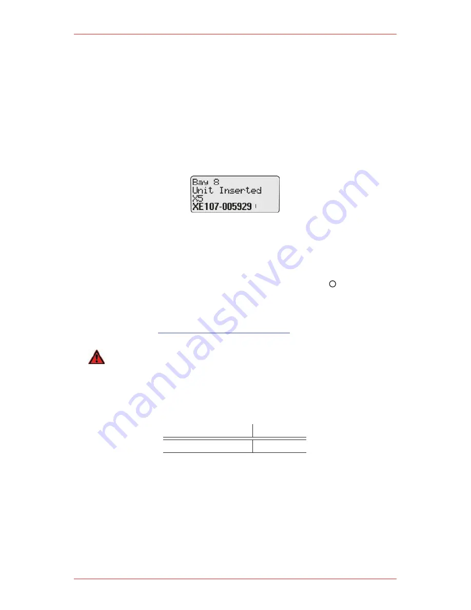
The station LCD displays the following docking module identification; the
type of detector that is inserted, and
•
bay and serial number of the docking module.
•
The X5 detector LCD displays Microdock.
To bypass the station identification screen, press any
6.
button on the
station.
Adding Another Docking Module
If required, refer to
How to Use the Base Station
before adding a docking
module.
WArNINg
Only one module can be connected at a time. Complete steps #1-19 for each
docking module that is added.
To add another docking module, refer to Table 11 and 12, Figure 8, 9, and 10, and
complete the following procedures:
Housing Assembly
Torque
Wall mounting plate
9-10 in lbs
Table 11. Torque Specifications
Summary of Contents for MicroDock II
Page 1: ...MicroDock II Operating Manual MICRODOCK II AUTOMATIC TEST AND CALIBRATION ...
Page 2: ......
Page 8: ...MicroDock II Automatic Test and Calibration Station 8 ...
Page 38: ...MicroDock II Automatic Test and Calibration Station 38 ...
Page 64: ...MicroDock II Automatic Test and Calibration Station 64 ...
Page 67: ......


