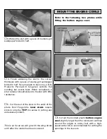


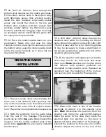


At this stage the model should be in ready-to-fly
condition with all of the systems in place
including the engine, landing gear, covering
and paint, and the radio system.
❏
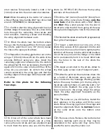
1. Use a felt-tip pen or 1/8" [3mm]-wide tape
to accurately mark the C.G. across the center
panel on the
bottom
of the
top wing
5-1/2"
[140mm] back from the leading edge.
❏
2. With the wing attached to the fuselage, all
parts of the model installed (ready to fly) and an
This is where your model should balance for
the first flights. Later, you may wish to
experiment by shifting the C.G. up to 1/4"
[6mm] forward or 1/4" [6mm] back to change
the flying characteristics. Moving the C.G.
forward may improve the smoothness and
stability, but the model may then require
more speed for takeoff and make it more
difficult to slow for landing. Moving the C.G.
aft makes the model more maneuverable, but
could also cause it to become too difficult to
control. In any case,
start
at
the
recommended balance point
and do not
at any time balance the model outside the
specified range.
More than any other factor, the
C.G
. (balance
point) can have the
greatest
effect on how a
model flies, and may determine whether or
not your first flight will be successful. If you
value this model and wish to enjoy it for
many flights,
DO NOT OVERLOOK THIS
IMPORTANT PROCEDURE.
A model that is
not properly balanced will be unstable and
possibly unflyable.
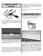
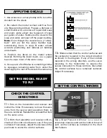
BALANCE THE MODEL (C.G.)
IMPORTANT:
The S.E.5a has been
extensively
flown and tested to arrive at the throws at
which it flies best. Flying your model at these
throws will provide you with the greatest
chance for successful first flights. If, after you
have become accustomed to the way the
S.E.5a flies, you would like to change the
throws to suit your taste, that is fine.
However, too much control throw could make
the model difficult to control, so remember,
“more is not always better.”
These are the recommended control
surface throws:
High Rate
Low Rate
ELEVATOR:
1-1/2" [38mm] up
3/4" [19mm] up
1-1/2" [38mm] down
3/4" [19mm] down
RUDDER:
1-1/2" [38mm] right
1" [25mm] right
1-1/2" [38mm] left
1" [25mm] left
AILERONS:
1-1/2" [38mm] up
1" [25mm] up
1-1/2" [38mm] down
1" [25mm] down
56
Summary of Contents for Dynaflite S.E.5a
Page 9: ...9 Die Drawing...
Page 10: ...10 Die Drawing...


