


18" [460mm] pushrod connected to the throttle
servo with a nylon clevis and connected to the
carburetor with a screw-lock pushrod connector.
❏
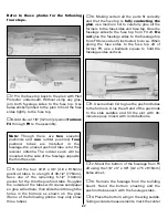
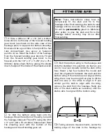
7. Make a
brace
for the aft end of the throttle
tube by drilling a 3/16" [4.8mm] hole through a
piece of leftover plywood and gluing it to F3
as shown.
❏
8. Drill 1/16" [1.6mm] holes through the fuse
top for the throttle servo screws. Run the servo
mounting screws in and out of the holes a few
times, remove the screws, then add a few drops
of thin CA to the holes and allow to fully
harden. Mount the servo in the fuselage with
the screws.
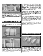
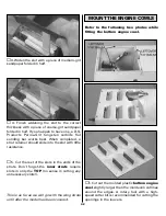
Refer to these photos while finishing the
engine compartment.
❏
9. Should you decide to use a remote fuel
filler and a remote glow plug hookup, mount
them and cut access holes for them where
necessary. A mount for the fuel filler like the
one in the photo could be made from leftover
1/8" [3.2mm] plywood, or the fuel filler could be
mounted directly to the fuselage side. Cut a
hole for the needle valve as well.
❏
10. Temporarily mount the muffler to see how
it fits in the fuselage. An O.S. MAX “in” type
exhaust header pipe (OSMG2624) was used on
this model to aim the exhaust downward without
having to cut holes in the fuselage sides.
❏
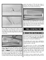
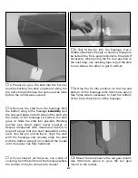
11. Cut the approximately 14" [360mm] piece
of triangle stock leftover from the top, center
wing panel into two pieces and glue them to
both sides of the front of the firewall and the
fuse sides.
❏
12. The same as was done for the tank tray,
glue together two pieces of 1/8" x 1/4" [3.2 x
6.4mm] basswood left over from the wing
spars. Cut the stick to the correct length and
glue it to the bottom of F1 along the aft edge
between the fuselage sides. Glue two more 1/8"
x 1/4" [3.2 x 6.4mm] basswood sticks along the
inside bottom edge of both fuselage sides
between the firewall and F1.
32
Summary of Contents for Dynaflite S.E.5a
Page 9: ...9 Die Drawing...
Page 10: ...10 Die Drawing...


