


❏
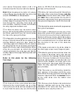
11. Mount the battery pack. It is suggested
that the battery pack be mounted as far forward
as practically possible to reduce or eliminate
the amount of lead ballast that may be required
in the nose. With the battery mounted where
shown, our prototype required approximately
8 oz. of weight in the nose. Make a mounting
plate from leftover plywood and balsa. Secure
the battery to the plate (with R/C foam rubber in
between) with Velcro, then securely glue the
balsa rails on the bottom of the plate to the
bottom of the fuselage behind the firewall (the
fuel tank must be removed to do this).
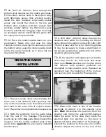
Refer to this photo for the following
three steps.
❏
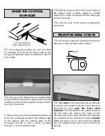
12. Mount the receiver. For this model a
removable mounting plate was made from
leftover plywood and screwed to leftover hard
balsa rails glued to the fuselage sides. The
receiver was mounted to the plywood plate
(with R/C foam in between) with rubber bands.
❏
13. Connect the servo wires and on/off switch
to the receiver and connect the battery to the
on/off switch. Connect the end of the “Y”
connector for the ailerons to the aileron plug in
the receiver (the remaining end of the “Y”
connector will be connected to the other “Y”
connector coming from the ailerons in the
bottom wing). Mount the on/off switch to the
side of the fuselage. For easy battery
monitoring and quick-charging, a Great Planes
Switch & Charge Jack Mounting Set (GPMM1000)
was used on this model.
❏
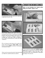
14. Route the antenna through the open guide
tube that doesn’t have any pushrods.
❏
1. Assemble and test fit the pilot. A William’s
Brother’s 1/4-Scale WWI Pilot (WBRQ2625) was
used in this model. Even though this S.E.5a is
closer to 1/5-scale, upon studying and test
fitting various sizes of pilots, it was decided that
the 1/4-scale pilot fits best and appears to be
most scale-like. Placing the pilot on a 2" x 2" [50
x 50mm] balsa block (not included) positions
him perfectly at the correct height.
❏
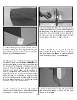
2. Paint the pilot and cockpit.
Optional:
The
cockpit can be “dressed-up” with Fourmost
Products #FOR 114 Regular Cockpit Coaming
(FORQ2014). Cut it to the length required, fit it
over the edges of the opening and glue it into
position with thin CA.
❏
3. Securely glue the pilot (and balsa block if
used) into position.
❏
4. Mount the headrest to the top of the
fuselage behind the pilot. A simple and secure
method is to use double-sided tape, but the
headrest could also be glued into position
FINISH THE COCKPIT
53
Summary of Contents for Dynaflite S.E.5a
Page 9: ...9 Die Drawing...
Page 10: ...10 Die Drawing...


