background image

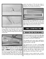
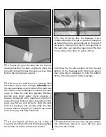
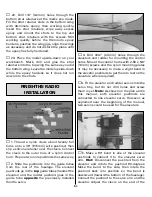
2. Glue tapered strips of leftover 1/16" [1.6mm]
balsa to the bottom of the fuselage sides so that
when  in  position,  the  aft  edge  of  the  bottom
cowl  will  be  even  with  the  bottom  fuselage
sheeting.

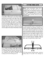
3. Glue leftover 1/4" [6.4mm] balsa sticks to the
firewall for the screws that secure the aft edge
of  the  bottom  cowl.  Fit  the  bottom  cowl  to  the
fuse,  sanding  the  edges  of  the  cowl  where
necessary for a good fit (this step will be easier
without the engine muffler in the way).

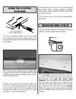
4. Drill 1/16" [1.6mm] holes through the bottom
cowl  into  the  bottom  of  the  fuselage.  Remove
the  cowl.  Enlarge  the  holes 

in  the  cowl

only

with  a  3/32"  [2.4mm]  drill.  Run  the  #2  x  3/8"
[9.5mm]  screws  in  and  out  of  the  holes  a  few
times to “cut” threads, then remove the screws
and add a few drops of thin CA to the holes and
allow to fully harden. Mount the bottom cowl to
the fuse with the screws and #2 washers.

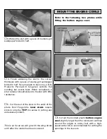
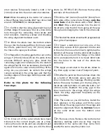
5. Cut out the bottom cowl to accommodate the
muffler.

❏ 

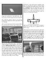
6.  Cut  out  and  test  fit  the  molded  plastic

front  engine  cowl

to  the  fuselage.  Drill  four

1/16"  [1.6mm]  holes  through  the  cowl  into  F1.
The bottom two holes should be centered in the
basswood stick on the back of F1. After drilling
the top two holes, glue pieces of leftover 1/8" x
1/4" [3.2 x 6.4mm] basswood to the back of F1
centered  over  the  holes.  Drill  1/16"  [1.6mm]
holes  through  the  basswood  pieces, “cut”  the
threads  with  another  #2  x  3/8"  [9.5mm]  screw,
and  harden  with  CA.  Enlarge  the  holes  in  the
cowl  only  with  a  3/32"  drill,  then  mount  the
front  cowl  with  four  #2  x  3/8"  [9.5mm]  screws
and #2 washers. 

In  addition  to  covering,  there  are  still  a  few
things that need to be done to finish the model
such  as  the  rest  of  the  radio  installation  and  a
few scale details like the pilot, dummy exhaust
pipes  and  finishing  the  wing  struts.  But  it’s
easiest  to  do  these  things  after  the  model  has
been covered.

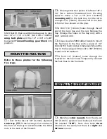
IMPORTANT:

The  following  instructions

illustrate how the S.E.5a on the kit box top was
covered. It was finished to resemble the S.E.5a
on 

the 

cover 

of 

the 

Squadron/Signal

Publications 

“S.E.5a  In Action” book. You  may

COVER THE MODEL

43

Summary of Contents for Dynaflite S.E.5a

Page 1: ...es the right to change or modify this warranty without notice In that Dynaflite has no control over the final assembly or material used for final assembly no liability shall be assumed nor accepted fo...

Page 2: ...READY TO FLY 55 Check the Control Directions 55 Set the ControlThrows 55 Balance the Model C G 56 Balance the Model Laterally 57 PREFLIGHT 57 IdentifyYour Model 57 Charge the Batteries 57 Balance the...

Page 3: ...than 1 5 scale The model featured on the kit box cover and in this instruction manual was finished similar to the one on the cover of the Squadron Publication s S E 5a in Action book No 1069 This book...

Page 4: ...check our web site at www dynaflite com for the latest S E 5a updates If you have not flown this type of model before we recommend that you get the assistance of an experienced pilot in your R C club...

Page 5: ...e Even with the O S MAX 91 four stroke the model was flown at reduced throttle settings much of the time If the S E 5a is powered by an engine in the upper end of the recommended size range prudent th...

Page 6: ...CAR0311 T pins small HCAR5100 medium HCAR5150 large large HCAR5200 3 16 4 8mm K S brass tube X Acto 240 razor saw XACR1440 Sanding tools and sandpaper assortment see Easy Touch Bar Sander section 21st...

Page 7: ...nders and replaceable Easy Touch Adhesive backed Sandpaper While building the S E 5a two 5 1 2 140mm Bar Sanders and two 11 280mm Bar Sanders equipped with 80 grit and 150 grit Adhesive backed Sandpap...

Page 8: ...Frequently you can study photos in following steps to get another view of the same parts Not all die cut parts have a name or their complete name stamped on them so refer to the die drawings on pages...

Page 9: ...9 Die Drawing...

Page 10: ...10 Die Drawing...

Page 11: ...ith Great Planes Plan Protector or wax paper so glue will not adhere to the plan 3 Use medium CA to build the fin from three 3 8 x 1 2 x 30 9 5 x 13 x 760mm balsa sticks and one 1 4 x 3 8 x 18 6 4 x 9...

Page 12: ...the corners off so they go in easier 9 Use a Great Planes Slot Machine to cut the hinge slots on the centerlines in the stab and elevators and in the fin and rudder where shown on the plan If you do...

Page 13: ...ife When using a hobby knife to cut hinge slots one of the most common mistakes made by modelers is making the slots too tight This restricts the flow of CA to the back of the hinges Another mistake m...

Page 14: ...outer ribs vertical as you glue 6 Glue the four die cut 1 8 3 2mm plywood inner bottom webs labeled IBW on the part to the spars and ribs where shown Glue the die cut 1 8 3 2mm plywood leading edge do...

Page 15: ...ter panel trailing edge 13 Cut out the bottom sheeting to accommodate the grooved 1 2 x 3 4 x 5 3 8 12 7 x 19 1 x 137mm basswood aft landing gear block Note the difference between the aft and the forw...

Page 16: ...nel is over your flat building board or cut it from the wing plan and cover it with Plan Protector or wax paper 2 The same as was done for the ribs on the ends of the bottom center panel cut partway t...

Page 17: ...r the leading edge of the left panel on the wing plan use medium CA to glue together the die cut 1 8 3 2mm plywood rib R4A the die cut 1 16 plywood rib R4B and the die cut 3 32 2 4mm balsa rib R4 Be c...

Page 18: ...f the remaining rib R3 that goes on the end of the outer panel you are working on Refer to this photo for the following two steps 12 Without using any glue add the following parts to the assembly Rib...

Page 19: ...d the sub leading edge to match the angle on the top of the ribs Refer to this photo for the following four steps 19 Cut the top leading edge sheet from a 3 32 x 3 x 24 2 4 x 76 x 610mm balsa sheet Gl...

Page 20: ...h rails as shown on the plan from the 1 8 x 1 2 x 18 3 2 x 12 7 x 460mm basswood stick then glue them into position Save the remainder of the stick for the servo hatch rails for the top panel 2 Place...

Page 21: ...he inside of the hatch Remove the hatch cover from the wing Use 30 minute epoxy to securely glue the servo mount blocks to the hatch with the servo arm centered in the slot Be certain the aft servo bl...

Page 22: ...n the forward and aft parts of the tip between the aileron spars and the aft spars 5 Center the trailing edge of the wing tip on the trailing edge of the wing Center the leading edge of the wing tip o...

Page 23: ...trailing edge and the aileron leading edge even with each other 11 The same as was done on the tail surfaces mark a centerline on the outer trailing edge On the model shown a ballpoint pen supported...

Page 24: ...to get them to fit Be certain the panels you are test fitting are matched up correctly bottom center panel to bottom outer panels 3 Lay the bottom center panel on your flat workbench Place weights on...

Page 25: ...by arrows in the top photo to tightly squeeze the panels together Use a few paper towel squares dampened with alcohol to wipe away any more epoxy that squeezes out of the joint Make certain the leadi...

Page 26: ...ries sand both assemblies flat and even 4 Switching to the fuselage bottom view build the fuselage top over the plan from the die cut 1 8 3 2mm plywood forward and aft fuselage tops FFT AFT and two 1...

Page 27: ...the fuse sides and fuse top Glue the fuselage sides to the fuse top from F3 aft Do not glue the fuselage sides to the fuselage top from F3 forward until instructed to do so When gluing the fuse sides...

Page 28: ...fuse Do not glue the dowels into the wing until instructed to do so 18 Glue both die cut 1 8 3 2mm plywood formers F2 together From now on this assembly will be referred to as the firewall 19 Drill 13...

Page 29: ...a length of 3 75mm Glue the rail to the back of former 3 as shown on the plan 3 Drill 1 16 1 6mm holes through the aft end of the tank tray and the rail Remove the tray Enlarge the holes in the tray o...

Page 30: ...he strut mounts 4 Test fit the strut mounts and four wing struts into the fuselage Slide the strut mounts as far upward into the slots in the fuselage top as they will go Use the die cut 1 8 3 2mm ply...

Page 31: ...em Mount the engine to the mount with 6 32 x 1 25mm screws and 6 lock washers and flat washers Now that the engine is mounted go ahead and hook up the throttle and do the rest of the hookups while the...

Page 32: ...uel filler like the one in the photo could be made from leftover 1 8 3 2mm plywood or the fuel filler could be mounted directly to the fuselage side Cut a hole for the needle valve as well 10 Temporar...

Page 33: ...4 x 1 4 x 24 6 4 x 6 4 x 610mm balsa stick Save the longer sticks for the aft end of the fuselage Glue the 4 1 2 115mm sticks into the notches of formers F5A and F6A Cut then sand the sticks even wit...

Page 34: ...kin where it is to be cut over the center of the 1 4 x 1 4 6 4 x 6 4mm stringer on the top of the formers Cut the skin at the marks then test fit and continue to cut as necessary to get it to fit well...

Page 35: ...g 1 8 x 1 4 3 2 x 6 4mm balsa sticks left over from step 3 and four more 1 8 x 1 4 x 24 3 2 x 6 4 x 610mm balsa sticks to make the stringers that run from F6B to F8B and glue them into position 1 Sand...

Page 36: ...the wing in alignment drill 7 or 13 64 holes through the aft landing gear block and the wing bolt plate inside the fuse at the marks made in step 4 Hint Make a drill jig by using a drill press to dril...

Page 37: ...t landing gear rail 1 Bolt the bottom wing to the fuselage and slide the stabilizer into position As best as you can for now just visually center the stab in the fuse Stand a few feet behind the model...

Page 38: ...fin onto the fuselage 4 Taking accurate measurements from side to side center the fin in the fuselage then glue pieces of leftover balsa to the top of the fuse holding the fin centered Be careful not...

Page 39: ...le the protruding portions of the blind nuts even with the outside of the tail gear mounts 3 Position the right mount over its location on the plan Mark the bottom of the rudder on the tail gear mount...

Page 40: ...if necessary to tack glue the other side of the aft wire to the forward wire 5 Make a 90 bend about 1 4 6 4mm from one of the 36 915mm pieces of the thin reinforcement wire included with this kit Tuc...

Page 41: ...ill be finished and mounted after the model has been covered 1 Using the patterns provided on the plan cut all eight wing struts from the 18 460mm airfoil shaped basswood sticks Note The patterns for...

Page 42: ...nce 5 Cut the rest of the slots in the ends of the struts Don t forget the inner struts require slots in only the TOP no sense in cutting any unnecessary slots This is as far as we will go with the wi...

Page 43: ...6 Cut out and test fit the molded plastic front engine cowl to the fuselage Drill four 1 16 1 6mm holes through the cowl into F1 The bottom two holes should be centered in the basswood stick on the ba...

Page 44: ...the cream to the bottom followed by the olive drab on top Cover the top and bottom of the elevators the same way Don t forget to cut the covering from the small vent holes to allow air to escape whil...

Page 45: ...ute a Y connector through the holes in the ribs in both wings Connect the Y connectors to the aileron servo wires then mount the servo hatches to the wing Secure the connections between the Y connecto...

Page 46: ...the covering from the fuselage where necessary so the balsa strips inside the exhaust pipes will contact bare balsa The wing struts are installed in the photo but should not yet be installed on your m...

Page 47: ...y align the stab with the bottom wing Do not disturb the model until the epoxy has fully hardened 4 If you haven t yet done so cut a strip of covering from the bottom of the fuselage where the bottom...

Page 48: ...to both sides of the hinges Keep a tissue nearby to absorb excess CA in case any seeps into the hinge gap or onto the wing 5 Join the rest of the control surfaces the same way 1 Cut the covering from...

Page 49: ...le they are holding onto the wings 7 Raise or lower the struts as necessary until they are contacting the bottom of the top wing and the leading and trailing edges of the wing are centered in the jigs...

Page 50: ...3 2mm hole 5 16 8mm from both ends of the outer struts Enlarge only the inner hole of all the struts with a 5 32 4mm drill Hint Slip a strut retainer into the slot in the strut to stop the drill from...

Page 51: ...the fuselage The elevator pushrods go in the top guide tubes nearest the elevator and the rudder pushrod goes in the guide tube opposite the previously installed throttle servo 3 Drill 3 32 2 4mm hol...

Page 52: ...nsert the screw into the wheel collar and tighten Remove the other screw add threadlocker reinsert and tighten 8 Connect the rudder pushrod to the rudder servo by making a 90 bend in the pushrod and f...

Page 53: ...he remaining end of the Y connector will be connected to the other Y connector coming from the ailerons in the bottom wing Mount the on off switch to the side of the fuselage For easy battery monitori...

Page 54: ...s show how to make one from a William s Brother s 16100 2 1 6 scale Lewis Aircraft Machine Gun kit WBRQ3561 and a few other various hobby materials Refer to this photo while making the machine gun and...

Page 55: ...e way 1 Turn on the transmitter and receiver and center the trims If necessary remove the servo arms from the servos and reposition them so they are centered Reinstall the screws that hold on the serv...

Page 56: ...not at any time balance the model outside the specified range More than any other factor the C G balance point can have the greatest effect on how a model flies and may determine whether or not your f...

Page 57: ...weight Begin by placing incrementally increasing amounts of weight on the top of the fuse over the firewall until the model balances Once you have determined the amount of weight required it can be pe...

Page 58: ...alancer GPMQ5000 in our flight box If the engine is new follow the engine manufacturer s instructions to break in the engine After break in confirm that the engine idles reliably transitions smoothly...

Page 59: ...ut off the fuel supply by closing off the fuel line or following the engine manufacturer s recommendations Do not use hands fingers or any other body part to try to stop the engine To stop a gasoline...

Page 60: ...Giant Scale R C aircraft are to have been flight tested and flight trimmed with a minimum of six flights before the model is allowed to fly at an IMAA Sanctioned event 3 5 Proof of Flight The complet...

Page 61: ...l tape heat shrink tubing or special clips suitable for that purpose 13 Make sure any servo extension cords you may have used do not interfere with other systems servo arms pushrods etc 14 Secure the...

Page 62: ...gently applying up elevator lifting the model into the air At this moment it is possible that additional right rudder will be required to counteract engine torque Be smooth on the elevator stick allo...

Page 63: ...e parallel with the runway Without crosswinds the S E 5a lands beautifully just the same as any other model However in a crosswind the model must be cross controlled so that its heading and trajectory...

Page 64: ..._____________ Where Purchased _________________________ Date Construction Started _________________ Date Construction Finished ________________ Finished Weight __________________________ Date of First...

Reviews: