88
10.
Communication Protocal
10.1
Communication Mode
1
.
Inverter communication protocol is Modbus protocol, and supports the common
register read and write
。
2
.
Drive as a slave, master-slave point to point communication. A Master drive uses
broadcast address to send a command, the slave does not answer.
3
.
In the case of long distance or multi-machine communication, we recommend to
connect the the master station signal GND with the drive signal "GND", in order to
improve the communication of immunity
10.2 Protocol Format
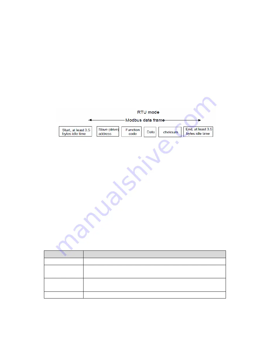
Modbus protocol supports RTU mode, the corresponding frame format is as follows,
Modbus adopts "Big Endian" encoding,firstly transmitting high byte, then low byte
。
RTU Mode
:
In RTU mode, idle time between frames will take the higher one among
Modbus internal conventional values and function code setting values. The
conventional Min idle frames inside Modbus is as follows: The idle time passed the
bus by the header and trailer is not less than 3.5 byte time.
Data verification uses CRC-16. The entire information participates in verification,
High&low bytes of checksum can be sent after exchanging. Specific CRC verification
can refer to the example associated with the protocol. It is worth noting, the idle
among frames should keep at least 3.5 bytes at the bus. The start and end idle among
frames at the bus need not to be accumulated
Through the function codes Drives can set different response delay to suit the specific
application needs of various master stations.In RTU mode, the actual response delay
is not less than 3.5 bytes intervals.
10.2
Protocol Function
Modbus main function is to read and write parameters. Different function codes apply
to different operation request. Inverter Modbus protocol supports the following
function codes
:
FunctionCodes
Description
0x03
Read inverter function code parameter and operating condition parameters
0x06
Modify single inverter function codes or control parameters , not saved
after power failure
0x10
Rewrite multiple function codes or control parameters , not saved after
power failure
0x41
Rewrite single drive or control parameters ,saved after power failure
Parameters of the inverter (Function code, control parameters and status parameters)
are mapped to Modbus read & write register. Read & write nature and scope of


