xx
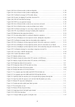
Figure 11-12 Output timing of the PCsOK signal (from STOP to RUN) ........................................................... 11-17
Figure 11-13 Output timing of the PCsOK signal (from RUN to STOP) ........................................................... 11-17
Figure 11-14 Timing of the STOP/RUN input signal (from OFF to ON) .......................................................... 11-18
Figure 11-15 Timing of the STOP/RUN input signal (from ON to OFF) .......................................................... 11-18
Figure 11-16 Timing of the RI/O STOP input signal (from OFF to ON) ........................................................... 11-19
Figure 11-17 Timing of the RI/O STOP input signal (from ON to OFF) ........................................................... 11-19
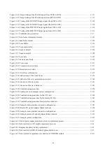
Figure 13-1 Troubleshooting procedure ............................................................................................................. 13-1
Figure 13-2 Error freeze information format ...................................................................................................... 13-23
Figure 13-3 Stack frame format .......................................................................................................................... 13-25
Figure 13-4 Trace buffer ..................................................................................................................................... 13-26
Figure 13-5 Trace control table .......................................................................................................................... 13-27
Figure 13-6 Usage example 1 ............................................................................................................................. 13-28
Figure 13-7 Usage example 2 ............................................................................................................................. 13-28
Figure 13-8 Trace data ........................................................................................................................................ 13-29
Figure 13-9 Frame header block ......................................................................................................................... 13-29
Figure 13-10 Trace cause .................................................................................................................................... 13-31
Figure 13-11 Transmission error status .............................................................................................................. 13-31
Figure 13-12 Reception error status .................................................................................................................... 13-32
Figure 13-13 Error freeze information ................................................................................................................ 13-35
Figure 13-14 Address map of the stack frame .................................................................................................... 13-36
Figure 13-15 Address of the error accumulation counters .................................................................................. 13-40
Figure 13-16 Structure of the trace area ............................................................................................................. 13-41
Figure 13-17 Structure of the trace data area ...................................................................................................... 13-42
Figure 13-18 Troubleshooting procedure ........................................................................................................... 13-50
Figure 13-19 Failed parts in an example system configuration ........................................................................... 13-51
Figure 13-20 Troubleshooting procedure for the PI/O unit ................................................................................ 13-84
Figure 13-21 Troubleshooting procedure for the remote I/O line ....................................................................... 13-85
Figure 13-22 Troubleshooting procedure for intermittent timeouts .................................................................... 13-86
Figure 13-23 Example station module connection configuration ....................................................................... 13-89
Figure 13-24 Remote I/O optical adapter failure locations ................................................................................. 13-90
Figure 13-25 Example station module connection configuration ....................................................................... 13-91
Figure 13-26 Example remote I/O optical adapter failure location .................................................................... 13-92
Figure 13-27 Example system configuration ...................................................................................................... 13-95
Figure 14-1 Parts of power supply module involved in replacement process ..................................................... 14-2
Figure 14-2 Parts involved in CPU module replacement process ....................................................................... 14-4
Figure 14-3 Diagram of primary battery replacement ........................................................................................ 14-8
Figure 14-4 Parts involved in RI/O-IF module replacement process .................................................................. 14-9
Figure 14-5 Parts involved in replacement or addition of OD.RING module .................................................... 14-11
Summary of Contents for S10VE
Page 1: ...User s Manual General Description SEE 1 001 A ...
Page 2: ...User s Manual General Description ...
Page 53: ...This page is intentionally left blank ...
Page 59: ...This page is intentionally left blank ...
Page 67: ...This page is intentionally left blank ...
Page 75: ...This page is intentionally left blank ...
Page 77: ...This page is intentionally left blank ...
Page 103: ...This page is intentionally left blank ...
Page 129: ...This page is intentionally left blank ...
Page 295: ...This page is intentionally left blank ...
Page 309: ...This page is intentionally left blank ...
Page 341: ...This page is intentionally left blank ...
Page 345: ...This page is intentionally left blank ...
Page 475: ...This page is intentionally left blank ...
Page 489: ...This page is intentionally left blank ...
Page 505: ......


