13. Troubleshooting
13-41
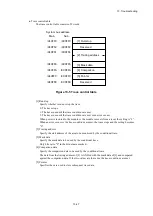
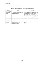
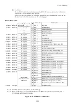
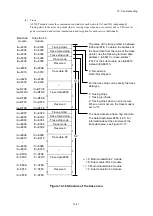
(6) Trace
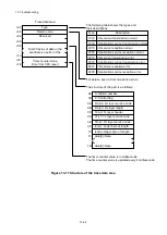
A J.NET module traces the communication status for each network (N1 and N2) independently.
Tracing starts in the error stop mode (that is, tracing stops when an error occurs) after a CPU reset or
power restoration and records transmission and reception for each service individually.
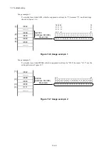
Figure 13-16 Structure of the trace area
Trace pointer
Trace forced stop
Trace stop code
Trace mode
Reserved
Trace data #0
~
Trace data #2FE
Reserved
Trace pointer
Trace forced stop
Trace stop code
Trace mode
Reserved
Trace data #0
~
Trace data #2FE
Reserved
~
~
~
~
~
~
~
~
~
~
~
~
~
~
~
~
~
~
~
~
~
~
~
~
~
~
~
~
The value of the trace pointer is between
/000 and /2FE. To obtain the address of
the trace data from the value of the trace
pointer, use the following formula: data
address = / (
trace-pointer
*
/20). For the sub module, use /AE8010
instead of /A68010.
0: Forced stop
Not 0: Not stopped
For the trace stop code, specify the trace
data type.
0: Tracing stops.
1: Tracing is infinite.
2: Tracing stops when an error occurs.
When an error occurs, the trace mode is
set to "0".
The trace data area has a ring structure.
The data that follows #2FE is #0. For
information about the structure of the
trace data area, see Figure 13-17.
△
= 6: Main module/Sub 2 module
= E: Sub module/Sub 3 module
□ = 7: Main module/Sub 2 module
= F: Sub module/Sub 3 module
N1
N2
~
/A□3FCE
/A□3FD0
~
/A□3FEE
/A□3FF0
~
/A□3FFE
/A
△
8030
~
/A
△
DFCE
/A
△
DFD0
~
/A
△
DFEE
/A
△
DFF0
~
/A
△
DFFE
/A
△
E000
/A
△
8000
/A
△
8002
/A
△
8004
/A
△
8006
/A
△
8008
~
/A
△
800E
/A
△
8010
~
/A
△
802E
/A
△
E002
/A
△
E004
/A
△
E006
/A
△
E008
~
/A
△
E00E
/A
△
E010
~
/A
△
E02E
/A
△
E030
Main/Sub
module
Sub 2/Sub 3
module
~
/C□3FCE
/C□3FD0
~
/C□3FEE
/C□3FF0
~
/C□3FFE
/C
△
8030
~
/C
△
DFCE
/C
△
DFD0
~
/C
△
DFEE
/C
△
DFF0
~
/C
△
DFFE
/C
△
E000
/C
△
8000
/C
△
8002
/C
△
8004
/C
△
8006
/C
△
8008
~
/C
△
800E
/C
△
8010
~
/C
△
802E
/C
△
E002
/C
△
E004
/C
△
E006
/C
△
E008
~
/C
△
E00E
/C
△
E010
~
/C
△
E02E
/C
△
E030
~
~
~
~
~
~
~
~
Summary of Contents for S10VE
Page 1: ...User s Manual General Description SEE 1 001 A ...
Page 2: ...User s Manual General Description ...
Page 53: ...This page is intentionally left blank ...
Page 59: ...This page is intentionally left blank ...
Page 67: ...This page is intentionally left blank ...
Page 75: ...This page is intentionally left blank ...
Page 77: ...This page is intentionally left blank ...
Page 103: ...This page is intentionally left blank ...
Page 129: ...This page is intentionally left blank ...
Page 295: ...This page is intentionally left blank ...
Page 309: ...This page is intentionally left blank ...
Page 341: ...This page is intentionally left blank ...
Page 345: ...This page is intentionally left blank ...
Page 475: ...This page is intentionally left blank ...
Page 489: ...This page is intentionally left blank ...
Page 505: ......

