background image

Section 4 - Operating the CFR 651

3. Set the upper deflector door.

-

Raise  or  lower  the  upper  deflector
door  to  adjust  the  amount  of
spreading of material.
-

Use the hydraulic cylinder to adjust
the door.

Note:  If  the  2  remote  option  is
installed,  the  door  cylinder  will  be
linked to the bale lift hydraulic circuit
through an electric solenoid
-  Move the electric selector valve so

the hydraulic flow goes to the door
cylinder.

Raised  -  material  will  be  spread  out
over a wide area - such as for bedding
materials.
-

Place the rubber deflector into the
tabs on the door.

Midway - deflector door will control the
height  and  distance  of  discharged
material.
-

Place the rubber deflector into the
tabs on the door. 

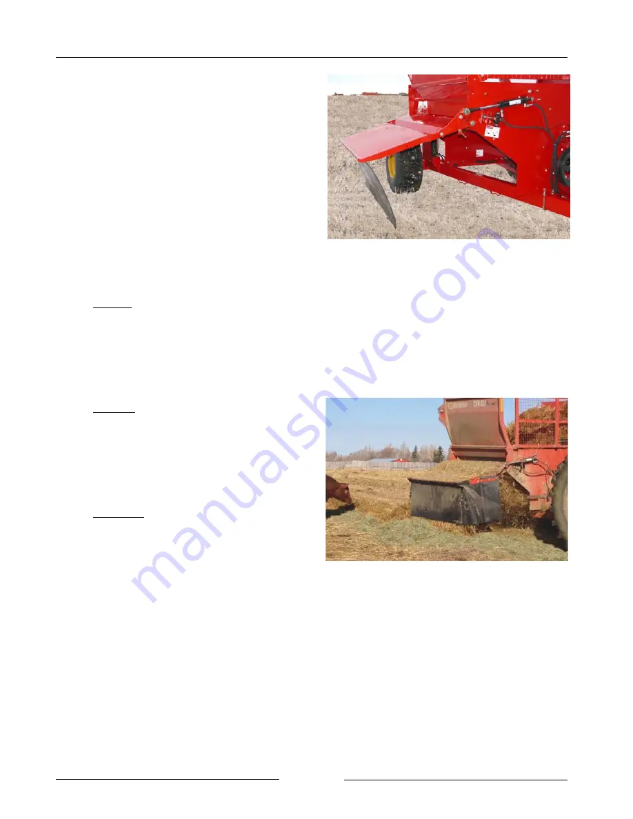
Lowered - the material will be left in a
windrow or directed into a feed bunk.
-

Allow the rubber deflector to hang
down.

Set the Upper Deflector Door 

(Windrowing Shown)

212005

Windrow Feeding

212121

Page 4-4

Summary of Contents for Bale Pro CFR651

Page 1: ...O p e r a t o r s M a n u a l E12033V3_A Bale Pro Complete Feed Ration CFR651...

Page 2: ...t 2018 by Highline Manufacturing Ltd All rights reserved The content of this manual was based on the most current information available as of the date of copyright It is the policy of Highline Manufac...

Page 3: ...ation of your Complete Feed Ration 651 CFR 651 In the manual you will find safety procedures maintenance routines and detailed operational instructions If you find that you require information not cov...

Page 4: ...level of the lower discharge door 4 Verify the position of the lower discharge door 5 Remove material around the feeder chain bearings 5 Check condition and tension of flail drum drive belt 6 Adjust t...

Page 5: ...bber into the tabs and fasten 3 Place the jack onto the hitch 4 Remove the driveline from the tractor PTO shaft 4 Disconnect the safety chain 4 Disconnect the hitch 4 Relieve the pressure on the hydra...

Page 6: ...deflector door allows the processed material to be laid down into a feed bunk windrow or spread to different distances The Complete Feed Ration 651 has the option of adding a Feed Chopper for additio...

Page 7: ...This Page Left Blank...

Page 8: ...ial number plate attached to the tub wall of the Complete Feed Ration 651 It is important to record the serial number for proof of ownership and for any service or maintenance assistance Serial Number...

Page 9: ...Operating and Maintenance information presented in this manual Do not operate or allow someone to operate this equipment until this information has been reviewed This information should be reviewed b...

Page 10: ...uation that if not avoided WILL result in DEATH OR SERIOUS INJURY The color is Red with White lettering Indicates a potentially hazardous situation that if not avoided COULD result in DEATH OR SERIOUS...

Page 11: ...s concern prudence and proper training of personnel involved in the operation transport maintenance and storage of the machine 3 The CFR 651 shall not be operated without all the guards in place SAFET...

Page 12: ...HILE FLAIL DRUM IS ROTATING Contact with rotating parts can cause serious injury or death Before removing the side panels Turn off the tractor and remove key Wait for all rotating parts to stop Ensure...

Page 13: ...he discharge area can cause serious injury or death Do not operate within 100 ft 30m of any person Keep all shields and guards in place ENSURE SLOW MOVING VEHICLE SIGN IS IN PLACE Ensure the Slow Movi...

Page 14: ...important information Allow only responsible properly instructed individuals to operate and service the machine Failure to follow the instructions and safety messages in this manual and on the decals...

Page 15: ...ious injury or death Relieve pressure on hydraulic system before repairing adjusting or disconnecting Wear proper hand and eye protection when searching for leaks Use wood or cardboard instead of hand...

Page 16: ...RE USING TWINE CUTTER Lock forks in the upright position before going under the raised forks Lock the flail drum to ensure no movement of the flail drum will occur while cutting twine or netwrap SHUTD...

Page 17: ...Section 1 Safety 216197 SAFETY DECAL LOCATIONS Page 1 10...

Page 18: ...ansport on public roads with bales in the processor tub Do not transport on public roads with a bale loaded on the forks Check with local traffic regulations to transport on public roads Stay away fro...

Page 19: ...ot attempt to operate the CFR 651 at a different PTO speed Note Do not use PTO adapters PTO adapters will cause a driveline failure and possible tractor damage Your CFR 651 warranty will also be inval...

Page 20: ...ty chain Ensure the safety chain rating is equal or greater than the gross weight of the loaded CFR 651 Route the safety chain around the lower safety chain bolt 1 Attach the chain to a secure locatio...

Page 21: ...pes easily and that the shields are in good condition and rotate freely Lift the tractor PTO shield Support the driveline pull back on the yoke collar align the splines by rotating the CFR 651 driveli...

Page 22: ...preference Route the hoses so they do not interfere with moving parts 10 Connect the lights Connect the light plug into the appropriate tractor receptacle Ensure the light cable does not interfere wi...

Page 23: ...Loosen the u bolts 1 that hold the axle tubes in place Slide the axle to achieve the desired wheel stance setting Note Maximum axle extension is 14 355 mm Axles may bend if extended beyond this amoun...

Page 24: ...draulic circuit through an electric solenoid Move the electric selector valve so the hydraulic flow goes to the door cylinder 17 Install the discharge deflector door transport lock Rotate the short li...

Page 25: ...e 20 Transport Do not transport on public roads with bales in the processor tub Do not transport on public roads with a bale loaded on the forks Do not transport on public roads with the forks in the...

Page 26: ...Ensure that the Slow Moving Vehicle SMV sign is clean and visible Shut down the tractor completely and set the parking brake Disconnect the PTO from the tractor before doing any work near the flail dr...

Page 27: ...rly See Section 5 Maintaining the CFR 651 for flail replacement information Replace the flails in pairs Replace on opposite sides of the drum to maintain drum balance Check the condition of the flail...

Page 28: ...der chain hydraulic motor to ensure the chain bars rotate freely 9 Check the tension of the feeder chain Shut down the tractor completely and set the parking brake Disconnect the PTO from the tractor...

Page 29: ...er Present The lower discharge door adjustment handle 1 is located on the rear tub wall There are 3 door positions The lowest position is often used for wet material or for a shorter throw distance Th...

Page 30: ...up around the feeder chain bearings These are accessed from the tub sidewalls Remove material from the upper feeder chain bearing Remove material from around the lower feeder chain bearing Remove mat...

Page 31: ...swing out of the way Check the condition of the drive belt Check the tension of the drive belt The tensioner should be set to the 25 degree mark For the procedures to adjust the tension of the drive...

Page 32: ...against the brace 1 For bales 5 feet 1 5 m in diameter Place both fork outer u bolts against the inside of the brace 2 For bales 4 feet 1 2 m in diameter Place both outer u bolts 3 a distance of 6 15...

Page 33: ...ssure on hydraulic system before repairing adjusting or disconnecting Visually inspect all the hydraulic hoses and fittings See Section 5 Maintaining the CFR 651 for conditions indicating that replace...

Page 34: ...spindle plate 19 Remove any twine that is built up around the axle spindle and hub Be careful to not damage the bearing grease seal while removing twine 20 Ensure the driveline shields are in place an...

Page 35: ...e the drum lock pin into the storage holder on the outside of the drive shield Fasten with the clip pin 22 Remove the fork cylinder lock and fasten onto the storage tab Note The forks may need to be r...

Page 36: ...lock is to be stored in the hole in the Grain Tank support 23 Remove the 2 nuts and washers 2 from the rubber panel 24 If the rubber deflector is going to be used in processing material remove the rub...

Page 37: ...ted by the hydraulic cylinder Note The cylinder may need to be moved with the hydraulics to remove the weight of the door from the lock 26 Lubricate all grease fittings and check the fluid level in al...

Page 38: ...and set the parking brake Disconnect the PTO from the tractor before doing any work near the flail drum Do not remove the side panels while flail drum is rotating Contact with rotating flail drum will...

Page 39: ...e path with the tub opening 1 6 Place the flail drum lock pin 2 into the tube on the front tub wall Allow the lock pin to slid into the processing chamber Manually rotate the flail drum until the lock...

Page 40: ...ade 9 Remove the twine cutter from the storage position The twine cutter is located on the rear of the bale tub 10 Insert the twine cutter with blade up Insert the twine cutter into the guide at the r...

Page 41: ...m Remove the drum lock pin from the flail drum drive plate tube 1 Note Failure to unlock the flail drum will result in damage to the machine during start up Place the drum lock pin into the storage ho...

Page 42: ...netwrap or twine from the flail drum 15 Replace the flail drum access panels Fasten in place with the panel pins 1 Secure with the clip pins 16 Remove the fork lock from the hydraulic cylinder and pl...

Page 43: ...Section 3 Preparing the CFR 651 This Page Left Blank Page 3 18...

Page 44: ...ting flail drum will cause serious injury or death Note Use caution if entering the tub with a bale in it even after all rotation has stopped The bale is unstable Stay back from an operating machine w...

Page 45: ...t the guard rods The amount of contact between the bale and the flails is determined by the guard rod setting There are five guard rod settings Pull the handle out of the handle lock Raise or lower th...

Page 46: ...chain revolutions per minute Chain Speeds Faster feeder chain speeds at the same aggression level setting will result in a faster discharge of material Slower feeder chain speeds at the same aggressi...

Page 47: ...electric selector valve so the hydraulic flow goes to the door cylinder Raised material will be spread out over a wide area such as for bedding materials Place the rubber deflector into the tabs on th...

Page 48: ...al or medium throw distance The highest position is often used for dry material longer throw and also for bunk feeding Snap the handle into a slot 2 Note When a Feed Chopper is present there are other...

Page 49: ...completely under the bale Raise the forks enough to lift the bale off the ground Note If a bale is frozen to the ground dislodge it by rocking the machine to impact the bale and loosen it Note Flail d...

Page 50: ...the PTO to engage the flail drum Stay clear from discharge side when PTO is engaged Do not operate within 100 ft 30m of any person Discharged material or objects leaving the discharge area can cause s...

Page 51: ...other causes of the vibration 9 Adjust the feeder chain speed and direction If loose material builds up near the top of the bale in the tub slow down the feeder chain to allow the flail drum to proces...

Page 52: ...ed Move the discharge rate lever Higher Number more material discharged Lower Number less material discharged 11 Re adjust the level of the lower discharge door if needed Snap the handle into a slot 2...

Page 53: ...damage by pushing the PTO into the tractor or into the drivebox or downward onto the PTO shaft breaking it off 14 Making turns Do not make turns sharper than 80 Angles greater than 80 can result in da...

Page 54: ...I Grade 2 grease Every 8 Hours PTO Lubricate 5 points on the PTO every 8 hours 1 point each constant velocity joint Continued angled operation will require lubrication every 4 hours 1 point on each jo...

Page 55: ...ricate 1 point on the lower feeder chain bearing on the outside rear of the tub Note When the Feed Chopper is present refer to the Feed Chopper Operator s manual Maintaining the Feed Chopper for infor...

Page 56: ...rs Visually Inspect Hydraulic Hoses Fittings Shut down the machine and replace the hydraulic hose assembly if any of the following conditions exist Fitting slippage on hose Damaged cracked cut or abra...

Page 57: ...adjustment nut 3 to change the chain tension Stand in the tub and hold the center of one of the feeder bars Lift the bar The bottom of the bar should be 1 from the plastic slider Verify the adjustment...

Page 58: ...t the Belt Tension Loosen the top nut 1 Place a socket wrench onto the nut 3 on the tension adjustment arm Take up the tension of the belt when the lower nut is loosened Loosen the lower nut that is w...

Page 59: ...the lower nut that is within the curved adjustment arc 2 Remove the drive belt from the tension pulley Move the anti rotation bolt 4 into one of the other holes in the mount bracket Tighten in place R...

Page 60: ...nts on the machine To change the drive belt 1 Remove the drive shield 2 Loosen the belt tensioner nut and rotate the tensionser to loosen the belt See information above for procedures 3 Remove 2 of 3...

Page 61: ...ns above 10 Replace the drive shield Check the Fluid Level in the Gearbox Check the oil fluid level by removing the oil level plug 1 in the center of the gearbox The oil should be at the level of the...

Page 62: ...ng servicing 1 Drain the oil from the gearbox Remove the drain plug on the bottom of the gearbox 1 Catch the oil in a container Allow the oil to drain completely from the gearbox 2 Replace the drain p...

Page 63: ...the nut 4 and bolt 5 that holds the flail 3 to the drum 1 2 Remove the pipe 2 inside the flail This pipe will be used again 3 Remove the flail that is on the opposite side of the flail drum Note To m...

Page 64: ...ire Pressure Fill the tires to 24 psi 165 kPa Transport speed should not exceed 25 mph 40 kmh When replacing the tires refer to the Specification Section for the size and type of tires Axles Check tha...

Page 65: ...ining the CFR 651 Remove any twine that is built up around the axle spindle and hub Be careful to not damage the grease seal on the bearing while removing twine Remove Twine From the Spindle and Hub 2...

Page 66: ...or coating to prevent weathering Do not enter the tub while the feeder chains are moving Injury and possible entrapment could occur from moving feeder chains Stop the tractor and remove the key Discon...

Page 67: ...the lock pin down firmly to ensure it is fully engaged into the flail drum 6 Remove any material that has built up around the feeder chain bearings Remove any material from the upper feeder chain bear...

Page 68: ...oor cylinder will be linked to the bale lift hydraulic circuit through an electric solenoid Move the electric selector valve so the hydraulic flow goes to the door cylinder 9 Install the discharge def...

Page 69: ...rted by the jack 12 Remove the driveline from the tractor PTO shaft Rest the driveline in the drive holder 13 Disconnect the safety chain from the tractor if present 14 Disconnect the hitch from the t...

Page 70: ...to keep them off the ground and clean 18 Place the driveline into the driveline support 19 Change the oil in the gearbox See Section 5 for the oil changing procedures Fill the gearbox to the oil level...

Page 71: ...Section 6 Storing the CFR 651 This Page Left Blank Page 6 6...

Page 72: ...ht to pull bale into tub Ensure forks are fully lowered prior to backing into the bale to prevent stabbing the bale The bale wrap would then prevent the bale from falling into the tub Bale falls throu...

Page 73: ...drive line Drive belt slipping Adjust drive belt tension Feeder chain not turning Tractor selective control valve not supplying enough hydraulic flow Increase the flow rate at the tractor selective c...

Page 74: ...loaded 1870 lbs 848 kg CFR With Feed ChopperTM Weight 6141 lbs 2786 kg Tongue weight Unloaded 2050 lbs 930 kg CFR With MGISTM Weight 6181 lb 2804 kg Tongue weight Unloaded 2190 lbs 993 kg CFR With Fee...

Page 75: ...Section 8 Specifications Tires 16 5LX 16 1 ANS Inflate to 24 psi Gearbox Oil Capacity 300 ml Page 8 2...

Page 76: ...APPLY TO 1 Any defect which was caused in Highline s sole judgement by other than normal use and service of the Equipment or by any of the following a accident b misuse or negligence c overloading d o...

Page 77: ...period will receive the balance of the one year New Equipment Limited Warranty Replacement parts after the original machine warranty are warranted to be free from defects of material for ninety 90 day...

Reviews: