


• Server in tower mode:
Position the tower server for hardware configuration.
Extend the server from the rack.
8. Remove any options installed in the PCIe3 expansion slots 1–4.
9. Proceed to Installing the TPM board and cover.
Installing the TPM board and cover
Procedure
1. Observe the following alerts:
CAUTION: If the TPM is removed from the original server and powered up on a different server, data stored in
the TPM including keys will be erased.
CAUTION: The TPM is keyed to install only in the orientation shown. Any attempt to install the TPM in a
different orientation might result in damage to the TPM or system board.
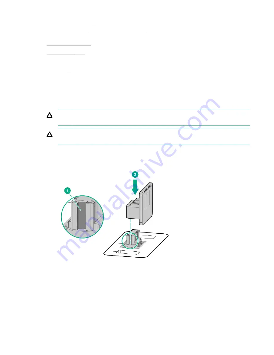
2. Align the TPM board with the key on the connector, and then install the TPM board. To seat the board, press the TPM
board firmly into the connector. To locate the TPM connector on the system board, see the server label on the access
panel.
3. Install the TPM cover:
a. Line up the tabs on the cover with the openings on either side of the TPM connector.
b. To snap the cover into place, firmly press straight down on the middle of the cover.
156
Hardware options installation
Summary of Contents for ProLiant ML350 Gen10
Page 28: ...NVMe drive bay numbering Tower orientation Rack orientation 28 Component identification ...
Page 31: ...Component identification 31 ...
Page 33: ...Open the front bezel Procedure 1 Unlock the front bezel 2 Open the front bezel Operations 33 ...
Page 178: ...Cable color Description Blue Front I O cable Orange Front USB cable 178 Cabling ...


