29
HEIDENHAIN TNC 426 B, TNC 430
Reference system
A reference system is required to define positions in a plane or in
space. The position data are always referenced to a predetermined
point and are described through coordinates.
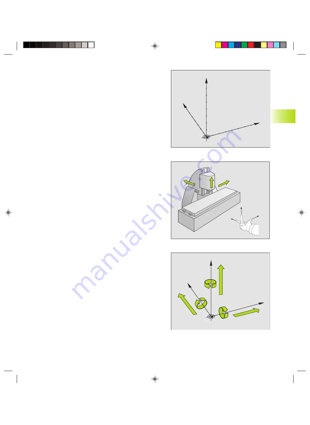
The Cartesian coordinate system (a rectangular coordinate system)
is based on three coordinate axes X, Y and Z. The axes are mutually
perpendicular and intersect at one point called the datum. A
coordinate identifies the distance from the datum in one of these
directions. A position in a plane is thus described through two
coordinates, and a position in space through three coordinates.
Coordinates that are referenced to the datum are referred to as
absolute coordinates. Relative coordinates are referenced to any
other known position (datum) you define within the coordinate
system. Relative coordinate values are also referred to as
incremental coordinate values.
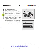
Reference systems on milling machines
When using a milling machine, you orient tool movements to the
Cartesian coordinate system. The illustration at right shows how
the Cartesian coordinate system describes the machine axes. The
figure at right illustrates the “right-hand rule” for remembering the
three axis directions: the middle finger is pointing in the positive
direction of the tool axis from the workpiece toward the tool (the Z
axis), the thumb is pointing in the positive X direction, and the index
finger in the positive Y direction.
The TNC 426 can control a machine tool in up to 5 axes; the TNC
430 controls up to 9 axes. The axes U, V and W are secondary linear
axes parallel to the main axes X, Y and Z, respectively. Rotary axes
are designated as A, B and C. The illustration at lower right shows
the assignment of secondary axes and rotary axes to the main axes.
4.1 Fundamentals of NC
W+
C+
B+
V+
A+
U+
Y
X
Z
Y
X
Z
+X
+Y
+Z
+X
+Z
+Y
Ekap4.pm6
30.06.2006, 07:03
29
www.EngineeringBooksPdf.com
Summary of Contents for TNC 426 B
Page 3: ...BAUSKLA PM6 30 06 2006 07 03 2 www EngineeringBooksPdf com ...
Page 4: ...BAUSKLA PM6 30 06 2006 07 03 3 www EngineeringBooksPdf com ...
Page 6: ...CINHALT PM6 30 06 2006 07 03 2 www EngineeringBooksPdf com ...
Page 16: ...CINHALT PM6 30 06 2006 07 03 12 www EngineeringBooksPdf com ...
Page 17: ...Introduction 1 Dkap1 pm6 30 06 2006 07 03 1 www EngineeringBooksPdf com ...
Page 29: ...Manual Operation and Setup 2 Dkap2_3 pm6 30 06 2006 07 03 13 www EngineeringBooksPdf com ...
Page 83: ...Programming Tools 5 Fkap5 pm6 30 06 2006 07 03 67 www EngineeringBooksPdf com ...
Page 106: ...Fkap5 pm6 30 06 2006 07 03 90 www EngineeringBooksPdf com ...
Page 107: ...Programming Programming Contours 6 Gkap6 pm6 30 06 2006 07 04 91 www EngineeringBooksPdf com ...
Page 165: ...Hkap7 pm6 30 06 2006 07 03 150 www EngineeringBooksPdf com ...
Page 166: ...Programming Cycles 8 kkap8 pm6 30 06 2006 07 03 151 www EngineeringBooksPdf com ...
Page 253: ...kkap8 pm6 30 06 2006 07 04 238 www EngineeringBooksPdf com ...
Page 265: ...LKAP9 PM6 30 06 2006 07 04 250 www EngineeringBooksPdf com ...
Page 266: ...Programming Q Parameters 10 MKAP10 PM6 30 06 2006 07 04 251 www EngineeringBooksPdf com ...
Page 297: ...MKAP10 PM6 30 06 2006 07 04 282 www EngineeringBooksPdf com ...
Page 298: ...Test Run and Program Run 11 NKAP11 PM6 30 06 2006 07 04 283 www EngineeringBooksPdf com ...
Page 312: ...MOD Functions 12 Okap12 pm6 30 06 2006 07 04 297 www EngineeringBooksPdf com ...
Page 332: ...Tables and Overviews 13 Pkap13 pm6 30 06 2006 07 04 317 www EngineeringBooksPdf com ...


