159
HEIDENHAIN TNC 426 B, TNC 430
ú
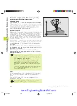
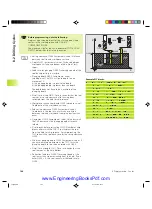
Disengaging direction (0/1/2/3/4) Q214: Determine the
direction in which the TNC retracts the tool at the hole
bottom (after spindle orientation).
0:
Do not retract tool
1:
Retract tool in the negative main axis direction
2:
Retract tool in the negative secondary axis direction
3:
Retract tool in the positive main axis direction
4:
Retract tool in the positive secondary axis direction
Danger of collision!
Check the position of the tool tip when you program a
spindle orientation to 0° (for example, in the Positioning
with Manual Data Input mode of operation). Align the
tool tip so that it is parallel to a coordinate axis. Select a
disengaging direction in which the tool moves away
from the edge of the hole.
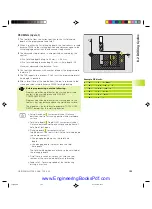
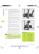
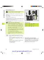
UNIVERSAL DRILLING (Cycle 203)
1
The TNC positions the tool in the tool axis at rapid traverse FMAX
to the programmed set-up clearance above the workpiece
surface.
2
The tool drills to the first plunging depth at the programmed feed
rate F.
3
If you have programmed chip breaking, the tool then retracts by
the setup clearance. If you are working without chip breaking, the
tool retracts at the RETRACTION FEED RATE to setup clearance,
remains there — if programmed — for the entered dwell time,
and advances again in FMAX to the setup clearance above the
first PLUNGING DEPTH.
4
The tool then advances with another infeed at the programmed
feed rate. If programmed, the plunging depth is decreased after
each infeed by the decrement.
5
The TNC repeats this process (2 to 4) until the programmed total
hole depth is reached.
6
The tool remains at the hole bottom — if programmed — for the
entered DWELL TIME to cut free, and then retracts to set-up
clearance at the retraction feed rate. If you have entered a 2nd
set-up clearance, the tool subsequently moves to that position in
FMAX.
8.2 Dr
illing Cy
cles
kkap8.pm6
30.06.2006, 07:03
159
www.EngineeringBooksPdf.com
Summary of Contents for TNC 426 B
Page 3: ...BAUSKLA PM6 30 06 2006 07 03 2 www EngineeringBooksPdf com ...
Page 4: ...BAUSKLA PM6 30 06 2006 07 03 3 www EngineeringBooksPdf com ...
Page 6: ...CINHALT PM6 30 06 2006 07 03 2 www EngineeringBooksPdf com ...
Page 16: ...CINHALT PM6 30 06 2006 07 03 12 www EngineeringBooksPdf com ...
Page 17: ...Introduction 1 Dkap1 pm6 30 06 2006 07 03 1 www EngineeringBooksPdf com ...
Page 29: ...Manual Operation and Setup 2 Dkap2_3 pm6 30 06 2006 07 03 13 www EngineeringBooksPdf com ...
Page 83: ...Programming Tools 5 Fkap5 pm6 30 06 2006 07 03 67 www EngineeringBooksPdf com ...
Page 106: ...Fkap5 pm6 30 06 2006 07 03 90 www EngineeringBooksPdf com ...
Page 107: ...Programming Programming Contours 6 Gkap6 pm6 30 06 2006 07 04 91 www EngineeringBooksPdf com ...
Page 165: ...Hkap7 pm6 30 06 2006 07 03 150 www EngineeringBooksPdf com ...
Page 166: ...Programming Cycles 8 kkap8 pm6 30 06 2006 07 03 151 www EngineeringBooksPdf com ...
Page 253: ...kkap8 pm6 30 06 2006 07 04 238 www EngineeringBooksPdf com ...
Page 265: ...LKAP9 PM6 30 06 2006 07 04 250 www EngineeringBooksPdf com ...
Page 266: ...Programming Q Parameters 10 MKAP10 PM6 30 06 2006 07 04 251 www EngineeringBooksPdf com ...
Page 297: ...MKAP10 PM6 30 06 2006 07 04 282 www EngineeringBooksPdf com ...
Page 298: ...Test Run and Program Run 11 NKAP11 PM6 30 06 2006 07 04 283 www EngineeringBooksPdf com ...
Page 312: ...MOD Functions 12 Okap12 pm6 30 06 2006 07 04 297 www EngineeringBooksPdf com ...
Page 332: ...Tables and Overviews 13 Pkap13 pm6 30 06 2006 07 04 317 www EngineeringBooksPdf com ...


