HEIDENHAIN TNC 426 B, TNC 430
285
1
1
.1 Gr
aphics
Limitations during program run
A graphical representation of a running program is not possible if
the microprocessor of the TNC is already occupied with
complicated machining tasks or if large areas are being machined.
Example: Multipass milling over the entire blank form with a large
tool. The TNC interrupts the graphics and displays the text ERROR
in the graphics window. The machining process is continued,
however.
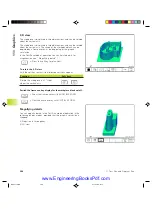
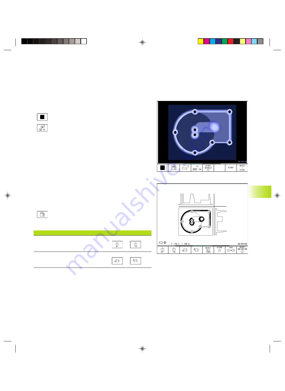
Plan view
ú
Press the soft key for plan view.
ú
Select the number of depth levels (after shifting the
soft-key row). You can choose between 16 or 32
shades of depth.
The deeper the surface, the darker the shade.
Plan view is the fastest of the three graphic display
modes.
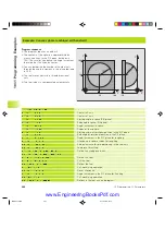
Projection in 3 planes
Similar to a workpiece drawing, the part is displayed with a plan
view and two sectional planes. A symbol to the lower left indicates
whether the display is in first angle or third angle projection
according to ISO 6433 (selected with MP7310).
Details can be isolated in this display mode for magnification (see
“Magnifying details”).
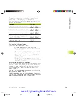
In addition, you can shift the sectional planes with the
corresponding soft keys:
ú
Press the soft key for projection in three planes.
ú
Shift the soft-key row until the TNC displays the
following soft keys:
Function
Soft keys
Shift the vertical sectional plane
to the right or left
Shift the horizontal sectional plane
upwards or downwards
The positions of the sectional planes are visible during shifting.
Coordinates of the line of intersection
At the bottom of the graphics window, the TNC displays the
coordinates of the line of intersection, referenced to the workpiece
datum. Only the coordinates of the working plane are shown. This
function is activated with machine parameter 7310.
NKAP11.PM6
30.06.2006, 07:04
285
www.EngineeringBooksPdf.com
Summary of Contents for TNC 426 B
Page 3: ...BAUSKLA PM6 30 06 2006 07 03 2 www EngineeringBooksPdf com ...
Page 4: ...BAUSKLA PM6 30 06 2006 07 03 3 www EngineeringBooksPdf com ...
Page 6: ...CINHALT PM6 30 06 2006 07 03 2 www EngineeringBooksPdf com ...
Page 16: ...CINHALT PM6 30 06 2006 07 03 12 www EngineeringBooksPdf com ...
Page 17: ...Introduction 1 Dkap1 pm6 30 06 2006 07 03 1 www EngineeringBooksPdf com ...
Page 29: ...Manual Operation and Setup 2 Dkap2_3 pm6 30 06 2006 07 03 13 www EngineeringBooksPdf com ...
Page 83: ...Programming Tools 5 Fkap5 pm6 30 06 2006 07 03 67 www EngineeringBooksPdf com ...
Page 106: ...Fkap5 pm6 30 06 2006 07 03 90 www EngineeringBooksPdf com ...
Page 107: ...Programming Programming Contours 6 Gkap6 pm6 30 06 2006 07 04 91 www EngineeringBooksPdf com ...
Page 165: ...Hkap7 pm6 30 06 2006 07 03 150 www EngineeringBooksPdf com ...
Page 166: ...Programming Cycles 8 kkap8 pm6 30 06 2006 07 03 151 www EngineeringBooksPdf com ...
Page 253: ...kkap8 pm6 30 06 2006 07 04 238 www EngineeringBooksPdf com ...
Page 265: ...LKAP9 PM6 30 06 2006 07 04 250 www EngineeringBooksPdf com ...
Page 266: ...Programming Q Parameters 10 MKAP10 PM6 30 06 2006 07 04 251 www EngineeringBooksPdf com ...
Page 297: ...MKAP10 PM6 30 06 2006 07 04 282 www EngineeringBooksPdf com ...
Page 298: ...Test Run and Program Run 11 NKAP11 PM6 30 06 2006 07 04 283 www EngineeringBooksPdf com ...
Page 312: ...MOD Functions 12 Okap12 pm6 30 06 2006 07 04 297 www EngineeringBooksPdf com ...
Page 332: ...Tables and Overviews 13 Pkap13 pm6 30 06 2006 07 04 317 www EngineeringBooksPdf com ...

