163
HEIDENHAIN TNC 426 B, TNC 430
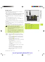
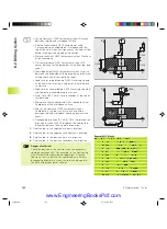
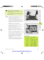
TAPPING with a floating tap holder (Cycle 2)
1
The tool drills to the total hole depth in one movement
2
Once the tool has reached the total hole depth, the direction of
spindle rotation is reversed and the tool is retracted to the
starting position at the end of the DWELL TIME.
3
At the starting position, the direction of spindle rotation reverses
once again.
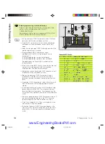
Before programming, note the following:
Program a positioning block for the starting point (hole
center) in the working plane with RADIUS
COMPENSATION R0.
Program a positioning block for the starting point in the
tool axis (set-up clearance above the workpiece surface).
The algebraic sign for the depth parameter determines
the working direction.
A floating tap holder is required for tapping. It must
compensate the tolerances between feed rate and
spindle speed during the tapping process.
When a cycle is being run, the spindle speed override
knob is disabled. The feed rate override knob is active
only within a limited range, which is defined by the
machine tool builder (refer to your machine manual).
For tapping right-hand threads activate the spindle with
M3, for left-hand threads use M4.
ú
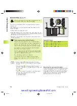
Setup clearance (incremental value): Distance
between tool tip (at starting position) and workpiece
surface. Standard value: approx. 4 times the thread
pitch
ú
Total hole depth (thread length, incremental value):
Distance between workpiece surface and end of
thread
ú
Dwell time in seconds: Enter a value between 0 and
0.5 seconds to avoid wedging of the tool during
retraction.
ú
Feed rate F: Traversing speed of the tool during
tapping
The feed rate is calculated as follows: F = S x p,
where
F is the feed rate in mm/min),
S is the spindle speed in rpm,
and p is the thread pitch in mm
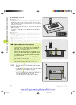
Retracting after a program interruption
If you interrupt program run during tapping with the machine stop
button, the TNC will display a soft key with which you can retract the
tool.
X
Z
8.2 Dr
illing Cy
cles
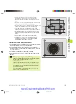
Example NC blocks:
13 CYCL DEF 2.0 TAPPING
14 CYCL DEF 2.1 SET UP 2
15 CYCL DEF 2.2 DEPTH -20
16 CYCL DEF 2.3 DWELL 0
17 CYCL DEF 2.4 F100
kkap8.pm6
30.06.2006, 07:03
163
www.EngineeringBooksPdf.com
Summary of Contents for TNC 426 B
Page 3: ...BAUSKLA PM6 30 06 2006 07 03 2 www EngineeringBooksPdf com ...
Page 4: ...BAUSKLA PM6 30 06 2006 07 03 3 www EngineeringBooksPdf com ...
Page 6: ...CINHALT PM6 30 06 2006 07 03 2 www EngineeringBooksPdf com ...
Page 16: ...CINHALT PM6 30 06 2006 07 03 12 www EngineeringBooksPdf com ...
Page 17: ...Introduction 1 Dkap1 pm6 30 06 2006 07 03 1 www EngineeringBooksPdf com ...
Page 29: ...Manual Operation and Setup 2 Dkap2_3 pm6 30 06 2006 07 03 13 www EngineeringBooksPdf com ...
Page 83: ...Programming Tools 5 Fkap5 pm6 30 06 2006 07 03 67 www EngineeringBooksPdf com ...
Page 106: ...Fkap5 pm6 30 06 2006 07 03 90 www EngineeringBooksPdf com ...
Page 107: ...Programming Programming Contours 6 Gkap6 pm6 30 06 2006 07 04 91 www EngineeringBooksPdf com ...
Page 165: ...Hkap7 pm6 30 06 2006 07 03 150 www EngineeringBooksPdf com ...
Page 166: ...Programming Cycles 8 kkap8 pm6 30 06 2006 07 03 151 www EngineeringBooksPdf com ...
Page 253: ...kkap8 pm6 30 06 2006 07 04 238 www EngineeringBooksPdf com ...
Page 265: ...LKAP9 PM6 30 06 2006 07 04 250 www EngineeringBooksPdf com ...
Page 266: ...Programming Q Parameters 10 MKAP10 PM6 30 06 2006 07 04 251 www EngineeringBooksPdf com ...
Page 297: ...MKAP10 PM6 30 06 2006 07 04 282 www EngineeringBooksPdf com ...
Page 298: ...Test Run and Program Run 11 NKAP11 PM6 30 06 2006 07 04 283 www EngineeringBooksPdf com ...
Page 312: ...MOD Functions 12 Okap12 pm6 30 06 2006 07 04 297 www EngineeringBooksPdf com ...
Page 332: ...Tables and Overviews 13 Pkap13 pm6 30 06 2006 07 04 317 www EngineeringBooksPdf com ...

