94
6 Programming: Programming Contours
Entering more than three coordinates
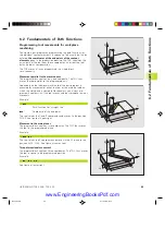
Machining with 5 axes, for example, moves 3 linear and 2 rotary
axes simultaneously.
Such programs are too complex to program at the machine,
however, and are usually created with a CAD system.
Example:
L X+20 Y+10 Z+2 A+15 C+6 R0 F100 M3
The TNC graphics cannot simulate movements in more
than three axes.
Circles and circular arcs
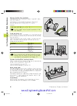
The TNC moves two axes simultaneously in a circular path relative
to the workpiece. You can define a circular movement by entering
the circle center CC.
When you program a circle, the TNC assigns it to one of the main
planes. This plane is defined automatically when you set the
spindle axis during a tool call:
Spindle axis
Main plane
Z
XY
, also
UV, XV, UY
Y
ZX
, also
WU, ZU, WX
X
YZ
, also
VW, YW, VZ
You can program circles that do not lie parallel to a main
plane by using the function for tilting the working plane
(see Chapter 8) or Q parameters (see Chapter 10).
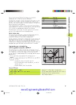
Direction of rotation DR for circular movements
When a circular path has no tangential transition to another contour
element, enter the direction of rotation DR:
Clockwise direction of rotation: DR–
Counterclockwise direction of rotation: DR+
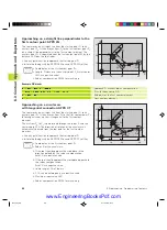
Radius compensation
The radius compensation must be in the block in which you move
to the first contour element. You cannot begin radius compensation
in a circle block. It must be activated beforehand an a straight-line
block or approach block (APPR block).
For detailed information on approach and straight-line blocks, refer
to sections 6.3 “Contour Approach and Departure” and 6.4 “Path
Contours — Cartesian Coordinates.”
Pre-positioning
Before running a part program, always pre-position the tool to
prevent the possibility of damaging it or the workpiece.
X
Y
X
Y
CC
X
CC
Y
CC
CC
CC
DR–
DR+
X
Z
Y
6.2 F
undamentals of P
ath F
unctions
Gkap6.pm6
30.06.2006, 07:04
94
www.EngineeringBooksPdf.com
Summary of Contents for TNC 426 B
Page 3: ...BAUSKLA PM6 30 06 2006 07 03 2 www EngineeringBooksPdf com ...
Page 4: ...BAUSKLA PM6 30 06 2006 07 03 3 www EngineeringBooksPdf com ...
Page 6: ...CINHALT PM6 30 06 2006 07 03 2 www EngineeringBooksPdf com ...
Page 16: ...CINHALT PM6 30 06 2006 07 03 12 www EngineeringBooksPdf com ...
Page 17: ...Introduction 1 Dkap1 pm6 30 06 2006 07 03 1 www EngineeringBooksPdf com ...
Page 29: ...Manual Operation and Setup 2 Dkap2_3 pm6 30 06 2006 07 03 13 www EngineeringBooksPdf com ...
Page 83: ...Programming Tools 5 Fkap5 pm6 30 06 2006 07 03 67 www EngineeringBooksPdf com ...
Page 106: ...Fkap5 pm6 30 06 2006 07 03 90 www EngineeringBooksPdf com ...
Page 107: ...Programming Programming Contours 6 Gkap6 pm6 30 06 2006 07 04 91 www EngineeringBooksPdf com ...
Page 165: ...Hkap7 pm6 30 06 2006 07 03 150 www EngineeringBooksPdf com ...
Page 166: ...Programming Cycles 8 kkap8 pm6 30 06 2006 07 03 151 www EngineeringBooksPdf com ...
Page 253: ...kkap8 pm6 30 06 2006 07 04 238 www EngineeringBooksPdf com ...
Page 265: ...LKAP9 PM6 30 06 2006 07 04 250 www EngineeringBooksPdf com ...
Page 266: ...Programming Q Parameters 10 MKAP10 PM6 30 06 2006 07 04 251 www EngineeringBooksPdf com ...
Page 297: ...MKAP10 PM6 30 06 2006 07 04 282 www EngineeringBooksPdf com ...
Page 298: ...Test Run and Program Run 11 NKAP11 PM6 30 06 2006 07 04 283 www EngineeringBooksPdf com ...
Page 312: ...MOD Functions 12 Okap12 pm6 30 06 2006 07 04 297 www EngineeringBooksPdf com ...
Page 332: ...Tables and Overviews 13 Pkap13 pm6 30 06 2006 07 04 317 www EngineeringBooksPdf com ...


