20
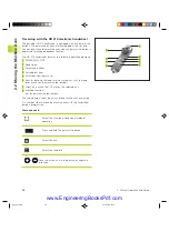
There are two functions available for tilting the working plane
■
3-D ROT soft key in the Manual mode and Electronic Handwheel
mode (described below)
■
Tilting under program control: Cycle 19 WORKING PLANE in the
part program: see „8.7 Coordinate Transformation Cycles“.
The TNC functions for “tilting the working plane” are coordinate
transformations in which the working plane is always perpendicular
to the direction of the tool axis.
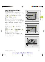
When tilting the working plane, the TNC differentiates between
two machine types
Machines with tilting tables:
■
You must tilt the
workpiece
into the desired position for
machining by positioning the tilting table, for example with an L
block.
■
The position of the transformed tool axis
does not change
in
relation to the machine-based coordinate system. Thus if you
rotate the table — and therefore the workpiece — by 90° for
example, the coordinate system
does not rotate
. If you press the
Z+ axis direction button in the Manual Operation mode, the tool
moves in Z+ direction.
■
In calculating the transformed coordinate system, the TNC
considers only the mechanically influenced offsets of the
particular tilting table (the so-called “translational” components).
Machines with swivel heads
■
You must bring the
tool
into the desired position for machining by
positioning the swivel head, for example with an L block.
■
The position of the transformed tool axis
changes
in relation to
the machine-based coordinate system. Thus if you rotate the
swivel head — and therefore the tool — in the B axis by 90° for
example,
the coordinate system rotates also
. If you press the
Z+ axis direction button in the Manual Operation mode, the tool
moves in X+ direction of the machine-based coordinate system.
■
In calculating the transformed coordinate system, the TNC
considers both the mechanically influenced offsets of the
particular swivel head (the so-called “translational” components)
and
offsets caused by tilting of the tool (3-D tool length
compensation).
2.5 T
ilting the
W
o
rking Plane
2 Manual Operation and Setup
Dkap2_3.pm6
30.06.2006, 07:03
20
www.EngineeringBooksPdf.com
Summary of Contents for TNC 426 B
Page 3: ...BAUSKLA PM6 30 06 2006 07 03 2 www EngineeringBooksPdf com ...
Page 4: ...BAUSKLA PM6 30 06 2006 07 03 3 www EngineeringBooksPdf com ...
Page 6: ...CINHALT PM6 30 06 2006 07 03 2 www EngineeringBooksPdf com ...
Page 16: ...CINHALT PM6 30 06 2006 07 03 12 www EngineeringBooksPdf com ...
Page 17: ...Introduction 1 Dkap1 pm6 30 06 2006 07 03 1 www EngineeringBooksPdf com ...
Page 29: ...Manual Operation and Setup 2 Dkap2_3 pm6 30 06 2006 07 03 13 www EngineeringBooksPdf com ...
Page 83: ...Programming Tools 5 Fkap5 pm6 30 06 2006 07 03 67 www EngineeringBooksPdf com ...
Page 106: ...Fkap5 pm6 30 06 2006 07 03 90 www EngineeringBooksPdf com ...
Page 107: ...Programming Programming Contours 6 Gkap6 pm6 30 06 2006 07 04 91 www EngineeringBooksPdf com ...
Page 165: ...Hkap7 pm6 30 06 2006 07 03 150 www EngineeringBooksPdf com ...
Page 166: ...Programming Cycles 8 kkap8 pm6 30 06 2006 07 03 151 www EngineeringBooksPdf com ...
Page 253: ...kkap8 pm6 30 06 2006 07 04 238 www EngineeringBooksPdf com ...
Page 265: ...LKAP9 PM6 30 06 2006 07 04 250 www EngineeringBooksPdf com ...
Page 266: ...Programming Q Parameters 10 MKAP10 PM6 30 06 2006 07 04 251 www EngineeringBooksPdf com ...
Page 297: ...MKAP10 PM6 30 06 2006 07 04 282 www EngineeringBooksPdf com ...
Page 298: ...Test Run and Program Run 11 NKAP11 PM6 30 06 2006 07 04 283 www EngineeringBooksPdf com ...
Page 312: ...MOD Functions 12 Okap12 pm6 30 06 2006 07 04 297 www EngineeringBooksPdf com ...
Page 332: ...Tables and Overviews 13 Pkap13 pm6 30 06 2006 07 04 317 www EngineeringBooksPdf com ...


