4
ADVANCED OPERATION EXAMPLE
APS-1102A
4-7
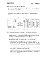
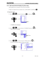
4.1.4 Setting the output voltage
The ranges that can be set are listed below.
Table4-3. Output Voltage Setting Ranges When AC+DC Mode Is Selected
Setting
Setting range
resolution
DC voltage
100 V range
220.0 to +220.0 V
0.1 V
200 V range
440.0 to +440.0 V
0.1 V
AC voltage
100 V range
SIN/SQU
0.0 to 155.0 Vrms
0.1 Vrms
ARB1 to ARB16
0.0 to 440.0 Vp-p
0.1 Vp-p
200 V range
SIN/SQU
0.0 to 310.0 Vrms
0.1 Vrms
ARB1 to ARB16
0.0 to 880.0 Vp-p
0.1 Vp-p
Output can be set so that AC voltage is superimposed on DC voltage.
The unit for AC voltage settings differs according to the AC voltage waveform setting.
When the selected AC voltage waveform is SIN/SQU, the AC voltage setting is in Vrms units, and
when it is ARB1 to ARB16, the setting is in Vp-p units.
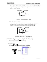
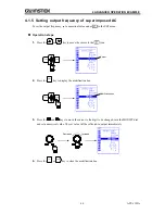
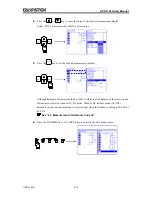
To select an output voltage, select
“DC voltage” or
“AC voltage” in the SET menu, then set
a numerical value.
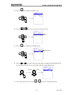
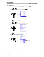
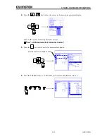
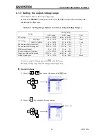
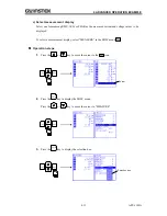
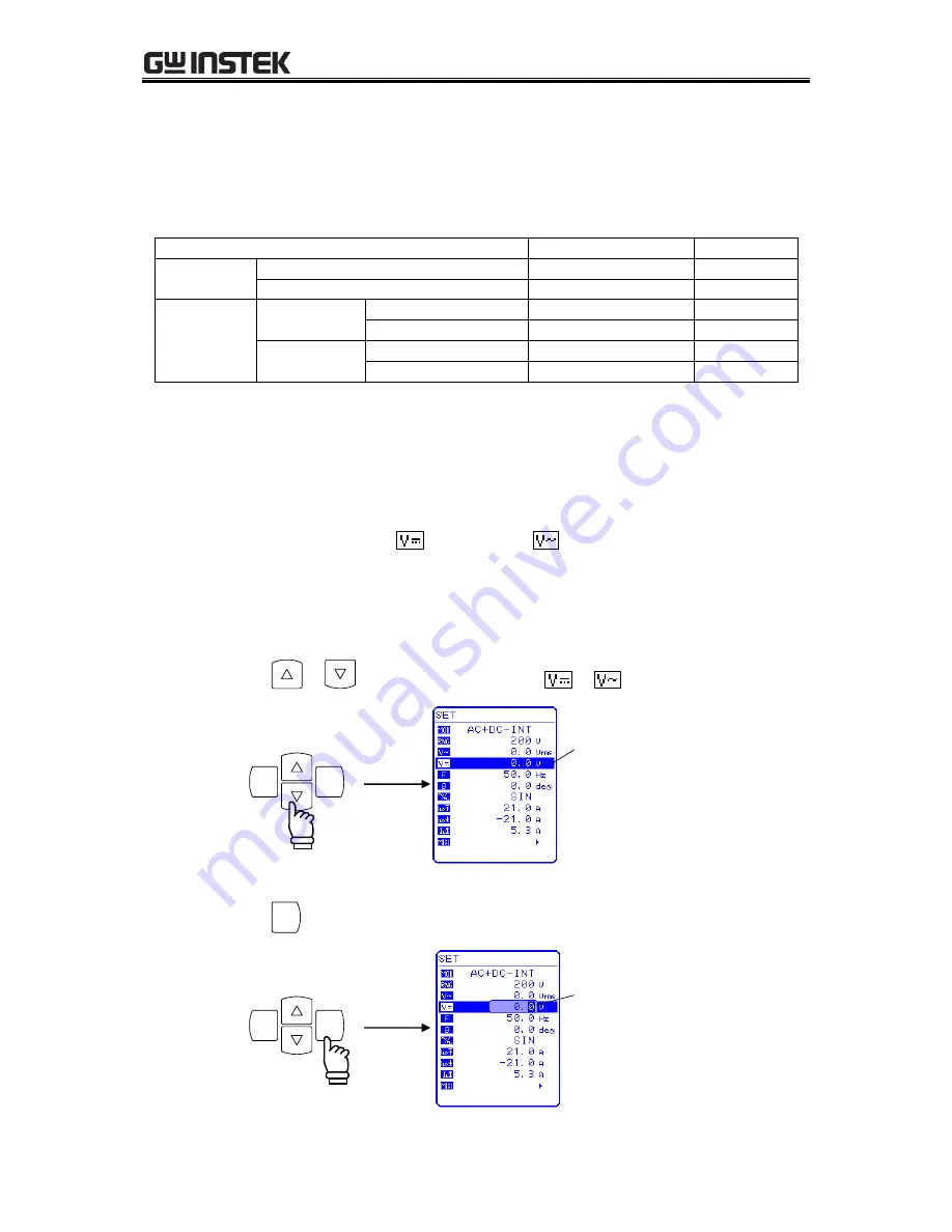
Operation steps
1.
Press the
or
key to move the cursor to the
or
icon.
ENTER
CANCEL
Cursor
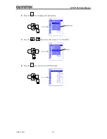
2.
Press the
EN TER
key to display the modification box.
ENTER
CANCEL
Modification box
Summary of Contents for APS-1102A
Page 15: ...Tables APS 1102A xiii ...
Page 16: ......
Page 24: ......
Page 72: ...APS 1102A User Manual APS 1102A 3 38 ...
Page 184: ...APS 1102A User Manual APS 1102A 5 50 ...
Page 242: ...APS 1102A User Manual APS 1102A 6 58 ...


