


APS-1102A User Manual
APS-1102A
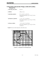
9-14
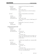
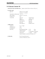
9.11 External Control I/O
a) External control operation mode
Enabled or disabled (the state output is always on)
b) Control input
Input level:
High level: +4.0 V or higher
Low level: +1.0 V or lower
Nondestructive maximum input: +10 V/
5 V
Input impedance:
pull-up to +5 V at 47 k
Detection cycle:
2 ms
Control items:
Output off
Output off at fall
Output on
Output on at fall
Sequence start
Start at fall
Stop of sequence
Stop at fall
Hold input
Hold at fall
Branch inputs 0, 1
Start branch at fall
c) State output
Output level:
0 V/+5 V (open)
Output impedance:
100 Ω
Switching cycle:
0.1 ms
Status items:
Power source on/off status
L: off,
H: on
Output on/off status
L: off,
H: on
Limiter operation
L: Not operating, H: Operating
Software busy
L: Normal,
H: Busy
Sequence operation step synchronized outputs L or H
d) Terminals
D-sub 25-pin multi-connector
(rear panel, female, M2.6 screw)
Summary of Contents for APS-1102A
Page 15: ...Tables APS 1102A xiii ...
Page 16: ......
Page 24: ......
Page 72: ...APS 1102A User Manual APS 1102A 3 38 ...
Page 184: ...APS 1102A User Manual APS 1102A 5 50 ...
Page 242: ...APS 1102A User Manual APS 1102A 6 58 ...