A. Flap Handles:
Normal positioning of the flaps is accomplished by a FLAP handle located
on the right side of the cockpit center pedestal. It has four detents that set
the flaps to each of its positions: UP (0°), 10°, Takeoff / Approach (T/O /
APPR [20°]) and DOWN (39°). The handle moves vertically into each
detent. At each detent, operating limit switches control electrical power to
the flap circuitry.
An EMER FLAP handle on the copilot’s side console mechanically controls
the flap selector valve if the normal flap control system malfunctions. The
handle moves vertically to select one of three detents: FLAPS UP,
NEUTRAL (no movement) or FLAPS DOWN. Before using the EMER
FLAP handle, however, the EMERG FLAP switch (just aft of the EMER
FLAP handle) must be in the EMERG position in order to bypass the
normal FLAP handle switches and flap follow-up switches.
If both the Combined and Utility hydraulic systems are not available, the
Auxiliary hydraulic system can be used to position the flaps using the AUX
pump. In this scenario, the normal FLAP handle would still be used.
During normal FLAP handle operation, both the FLAP CONT and MANUAL
FLAP CONT circuit breakers must be set. During EMER FLAP handle
operation, only the MANUAL FLAP CONT circuit breaker must be set.
B. Flap Shutoff Valve:
A normally closed (spring-loaded) shutoff valve controls hydraulic fluid flow
to the flap selector valve. Electrically controlled by the flap control relay and
the follow-up switches, the valve is energized open to allow fluid flow to the
selector valve.
If an asymmetrical flap condition occurs, the flap asymmetry switches open
the flap control relay to de-energize the flap shutoff valve and stop
hydraulic pressure flow to the flap selector valve. Flap movement ceases at
this point.
C. Flap Selector Valve:
The solenoid-operated flap selector valve directs hydraulic pressure flow to
the hydraulic motor. When electrically actuated by the FLAP handle, one of
the valve’s two solenoids energizes to supply hydraulic pressure to the
hydraulic motor to drive it in the required direction to extend or retract the
flaps. When the flaps reach the commanded position, flap follow-up
switches de-energize the flap selector valve through the control relay.
Hydraulic pressure flow to motor is shut off and the motor stops.
Two flow regulators limit hydraulic fluid flow to the hydraulic motor to 2.6
Gallons Per Minute (GPM) and from the motor to return at 2.9 GPM.
D. Hydraulic Motor and Central Gearbox:
A fixed-displacement hydraulic motor powered by the Combined, Utility or
Auxiliary hydraulic systems provides power to the flap system central
gearbox. The gearbox employs 8.22:1 reduction gears to provide a 730
RPM output that drives the flap actuators.
The gearbox has three output shafts that drive the left and right flap
actuators and the horizontal stabilizer actuator. An additional output shaft
drives the flap follow-up switch assembly and flap position transmitter.
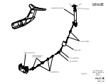
Multi-section torque shafts transmit rotational force from the gearbox to the
OPERATING MANUAL
PRODUCTION AIRCRAFT SYSTEMS
2A-27-00
Page 56
January 31/02
Revision 6
Summary of Contents for IV
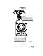
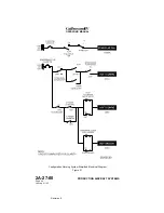
Page 17: ...Pitch Trim Controls Figure 5 OPERATING MANUAL 2A 27 00 Page 21 22 January 31 02 ...
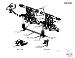
Page 32: ...Rudder Pedals Forward Linkage Figure 13 OPERATING MANUAL 2A 27 00 Page 39 40 January 31 02 ...
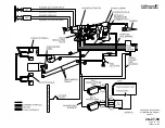
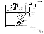
Page 50: ...Flaps Simplified Block Diagram Figure 18 OPERATING MANUAL 2A 27 00 Page 61 62 January 31 02 ...

