background image

J. Flap Control Circuit Breakers:

The FLAP CONT circuit breaker incorporates a switch which closes if the
breaker opens (manually pulled or popped). Power through the closed
MANUAL FLAP CONT circuit breaker and asymmetry switches will then
energize the flap control relay. The flap control relay, in turn, energizes the
flap shutoff valve open and hydraulic pressure flows to the flap selector
valve. In this configuration, the EMER FLAP handle can be used to select
flap position. If the MANUAL FLAP CONT circuit breaker opens (manually
pulled or popped), both normal and emergency operation of the flaps is
inhibited.

K. Flap Operational Description:

(1) Normal Operation:

Moving the FLAP handle from one detent to another actuates one of
the four handle switches associated with the selected flap position.
The switch closes and power is routed through a follow-up switch
associated with the desired flap position and direction (e.g., down to
10°) to the flap control relay through flap asymmetry switches.

If the flaps are symmetrical, the flap control relay energizes. The flap
shutoff relay energizes to the open position and the flap selector
valve shifts to the extend or retract position. Combined, Utility or
Auxiliary hydraulic system pressure then flows through the open
shutoff valve to the selector valve, which directs pressure through
flow regulators to the appropriate side of the hydraulic motor.

As the hydraulic motor turns, it drives the flaps in the desired
direction through the central gearbox, torque shafts and screwjacks.
The central gearbox at the same time also drives the horizontal
stabilizer to the desired setting to maintain longitudinal stability.

When the flaps reach the desired position, the follow-up switch
opens, breaking the circuit to the flap control relay. The relay
de-energizes to close the flap shutoff valve and the flap selector
valve is de-energized closed. Hydraulic pressure stops and the flaps
stop moving.

(2) Emergency Operation:

Placing the EMERG FLAP switch to EMERG deactivates the normal
FLAP handle and follow-up switches to allow direct control of the
flap control relay. A red X appears on both the pilot’s and copilot’s
normalized AOA display (lower left portion of the Primary Flight
Display [PFD]). The flap control relay energizes to open the flap
shutoff valve and hydraulic pressure flows to the flap selector valve.
Flap asymmetry protection is still provided because flap control
relay power is routed through the asymmetry switches.

Moving the EMER FLAP handle from NEUTRAL to the FLAPS UP
or FLAPS DOWN position directs hydraulic pressure through the
flap selector valve to the hydraulic motor. The motor operates and
the flaps move. When the flaps reach the desired position, moving
the EMER FLAP handle to NEUTRAL stops the flaps.

3. Controls and Indications:

(See Figure 17.)

OPERATING MANUAL

PRODUCTION AIRCRAFT SYSTEMS

2A-27-00

Page 59

January 31/02

Revision 6

Summary of Contents for IV

Page 1: ...light controls shown in Figure 1 include flaps ground spoilers and speedbrakes These flight controls are hydraulically powered and electrically or mechanically controlled The mechanically operated horizontal stabilizer moves in conjunction with the flaps to maintain longitudinal trim An Angle of Attack AOA system provides outputs to the control column shakers control column pusher approach indexer...

Page 2: ...OPERATING MANUAL THIS PAGE IS INTENTIONALLY LEFT BLANK PRODUCTION AIRCRAFT SYSTEMS 2A 27 00 Page 2 January 31 02 ...

Page 3: ...GIV Flight Controls Aerodynamic Axes Figure 1 OPERATING MANUAL 2A 27 00 Page 3 4 January 31 02 ...

Page 4: ...GIV Flight Controls Fluid Power Diagram Figure 2 OPERATING MANUAL 2A 27 00 Page 5 6 January 31 02 ...

Page 5: ...ontrol column pusher approach indexers normalized AOA display and stall barrier system The control column shakers provides early warning of a stall scenario by vibrating the control column before the stall while the control column pusher automatically initiates lowering the nose if the stall is imminent On CAA certified aircraft a flight control automatic failure detection system compares control ...

Page 6: ...low airspeeds C Hydraulic Boost System The elevator actuator is a dual tandem actuator consisting of two pistons secured to a common shaft The pistons move inside a common cylinder divided to create two separate cylinders One cylinder receives Flight hydraulic system pressure while the other cylinder receives Combined hydraulic system pressure Mechanical movement of the actuator input lever moves ...

Page 7: ...power shutoff valve With the valve closed operating pressure is removed from the actuator allowing the piston to idle The resultant advantage of the flight power shutoff provision is the ability to bypass a malfunctioning actuator such as would be the need in the unlikely event of an actuator jam and manually fly the aircraft Although control column effort and response time to inputs are increased...

Page 8: ...ormally checked by the flight crew on the first flight of the day during the Before Starting Engines checklist A check usually consists of running the elevator trim fully up then fully down using normal methods i e using both halves of the switch simultaneously This is followed by attempting to run the pitch trim using each half of the switch alone Any movement resulting from using either half of ...

Page 9: ...ndensation within the transducer case 2 AOA Display and Approach Indexer AOA display data supplied by the probes includes the normalized AOA display and the approach indexer Normalized AOA display is shown on the lower left portion of the Primary Flight Display PFD and consists of a vertical scale marked from 0 2 to 1 1 in 0 1 increments At the bottom of the scale is a three digit display surround...

Page 10: ...tuating cylinder As the cylinder extends it applies an input to the elevator actuator input sector This input causes the elevator actuator to drive the elevator trailing edges down the control column drives forward accordingly to approximately one inch forward of neutral When AOA has decreased more than one degree the stall barrier system disengages The force generated by the stall barrier system ...

Page 11: ...o activate the control column pusher NOTE Another momentary push of the TEST function key may be required to ensure the AOA indicator is in the normal area prior to takeoff G Failure Detection System CAA Certified Aircraft Only A flight control automatic failure detection system monitors flight control inputs from the control columns and compares them to the elevator actuator outputs If the system...

Page 12: ...RRIER 1 CPO A 9 Essential DC Bus STALL BARRIER 2 CPO B 9 R Main DC Bus STALL WARN CMPTR 1 CPO A 11 Essential DC Bus STALL WARN CMPTR 2 CPO B 11 R Main DC Bus ELEV COMB HYD S O 1 CPO B 15 Essential DC Bus ELEV FLT HYD S O 1 CPO A 15 Essential DC Bus ELEV TRIM TAB ACTR HTR 2 CP L 9 L Main AC Bus φC NOTE S 1 CAA certified aircraft only 2 SN 1380 subs SN 1000 1379 having ASC 342 B Warning Red Messages...

Page 13: ...Attack AOA may be used as reference but does not replace airspeed as the primary reference 2 Indication Parameters AOA indication must be within white band once forward airspeed is attained during takeoff roll 3 Use As A Speed Reference AOA shall not be used as a speed reference for takeoff rotation B Stall Barrier Stall Warning 1 Takeoff Requirements Both stall warning stall barrier systems must ...

Page 14: ...1 000 ft D Mach Trim Electric Elevator Trim Inoperative Speed With both mach trim compensators inoperative or electric elevator trim inoperative the maximum operating limit speed is 0 75 MT OPERATING MANUAL PRODUCTION AIRCRAFT SYSTEMS 2A 27 00 Page 16 January 31 02 Revision 6 ...

Page 15: ...Pitch Flight Control System Simplified Block Diagram Figure 3 OPERATING MANUAL 2A 27 00 Page 17 18 January 31 02 ...

Page 16: ...Stall Barrier Angle of Attack Wiring Schematic Figure 4 OPERATING MANUAL 2A 27 00 Page 19 20 January 31 02 ...

Page 17: ...Pitch Trim Controls Figure 5 OPERATING MANUAL 2A 27 00 Page 21 22 January 31 02 ...

Page 18: ...Stall Barrier Angle of Attack Controls and Indications Figure 6 OPERATING MANUAL 2A 27 00 Page 23 24 January 31 02 ...

Page 19: ...Control Columns Figure 7 OPERATING MANUAL PRODUCTION AIRCRAFT SYSTEMS 2A 27 00 Page 25 January 31 02 Revision 6 ...

Page 20: ...FLIGHT POWER SHUT OFF Handle Figure 8 OPERATING MANUAL PRODUCTION AIRCRAFT SYSTEMS 2A 27 00 Page 26 January 31 02 Revision 6 ...

Page 21: ...Yaw Damper Pitch Trim Control Panel Figure 9 OPERATING MANUAL PRODUCTION AIRCRAFT SYSTEMS 2A 27 00 Page 27 January 31 02 Revision 6 ...

Page 22: ...Stall Barrier Simplified Block Diagram Figure 10 OPERATING MANUAL PRODUCTION AIRCRAFT SYSTEMS 2A 27 00 Page 28 January 31 02 Revision 6 ...

Page 23: ...Stall Barrier Angle of Attack Warning Parameters Figure 11 OPERATING MANUAL PRODUCTION AIRCRAFT SYSTEMS 2A 27 00 Page 29 January 31 02 Revision 6 ...

Page 24: ...ransparent to the flight crew and can be made simultaneously with other inputs from the flight crew On CAA certified aircraft a flight control automatic failure detection system compares rudder pedal inputs to rudder actuator outputs If a malfunction is detected the system shuts off either or both hydraulic power sources to the actuator The yaw flight control system consists of the following subsy...

Page 25: ... actuator servo control valve through an input crank arm C Hydraulic Boost System See Figure 12 The rudder actuator is a dual tandem actuator consisting of two pistons secured to a common shaft The pistons move inside a common cylinder divided to create two separate cylinders One cylinder receives Flight hydraulic system pressure while the other cylinder receives Combined hydraulic system pressure...

Page 26: ...f the flight power shutoff provision is the ability to bypass a malfunctioning actuator such as would be the need in the unlikely event of an actuator jam and manually fly the aircraft Although rudder pedal effort and response time to inputs are increased while in manual reversion the aircraft remains capable of positive and harmonious control E Rudder Load Limiting System See Figure 12 Load limit...

Page 27: ...ndency within the aircraft The system is referred to as a series mode system in that no feedback is provided through the rudder pedals The yaw damper system consists of a solenoid operated shutoff valve transfer valve servo ram and summing lever transducer Electrical power is supplied to the system through the Right Main and Essential 28 VDC buses Hydraulic power is supplied to the system by the F...

Page 28: ... 10 units 7 5 NOSE R right of rudder deflection from the neutral position H Failure Detection System CAA Certified Aircraft Only A flight control automatic failure detection system monitors flight control inputs from the rudder pedals and compares them to the rudder actuator outputs If the system detects a failure it automatically shuts off hydraulic pressure to the actuator and triggers the appro...

Page 29: ... the rudder actuator SNGL RUDDER LIMIT Failure of input pressure load limiter with Flight and Combined Hydraulic System pressure normal YAW DAMPER OFF Yaw damper YAW DAMP ENG DISENG switch is OFF OR Yaw damper failure NOTE S 1 CAA certified aircraft only C Advisory Blue Messages and Annunciations CAS Message Cause or Meaning RUDDER LIMIT Rudder actuator torque limiter is in operation 4 Limitations...

Page 30: ...ion must be ON during all flight operations except as provided for in Section 05 03 40 Mach Trim Compensation Failure 2 If mach trim compensation failure is coupled with yaw damper failure When mach trim compensation failure is coupled with yaw damper failure observe speed limitations for both failures and limit altitude to 41 000 ft OPERATING MANUAL PRODUCTION AIRCRAFT SYSTEMS 2A 27 00 Page 36 Ja...

Page 31: ...Yaw Flight Control System Simplified Block Diagram Figure 12 OPERATING MANUAL 2A 27 00 Page 37 38 January 31 02 ...

Page 32: ...Rudder Pedals Forward Linkage Figure 13 OPERATING MANUAL 2A 27 00 Page 39 40 January 31 02 ...

Page 33: ...Yaw Trim Roll Trim Control Wheels Figure 14 OPERATING MANUAL PRODUCTION AIRCRAFT SYSTEMS 2A 27 00 Page 41 January 31 02 Revision 6 ...

Page 34: ...in flush to the wing as the opposite aileron travels downward Spoiler travel varies in proportion to the degree of the roll to maximum extension of 26 2 55 4 3 with speed brakes extended The flight spoiler system is solely a hydraulically powered system thus reversion to manual control is not possible A roll trim system is used to position a trim tab attached to the trailing edge of the left ailer...

Page 35: ...r consisting of two pistons secured to a common shaft The pistons move inside a common cylinder divided to create two separate cylinders One cylinder receives Flight hydraulic system pressure while the other cylinder receives Combined hydraulic system pressure Mechanical movement of the actuator input lever moves the servo control valve from its neutral position The servo control valve then direct...

Page 36: ...l control If the speed brakes are extended the flight spoilers extend up to a maximum of 55 4 3 As the aileron control mechanism commands an aileron to deflect upward the mixing linkage transmits an extend command to the flight spoiler actuator control valve through push pull rods bellcranks and cables The control valve then shifts to direct pressure to the flight spoiler actuator The normally ext...

Page 37: ...reased control inputs being applied by the flight crew If these control inputs exceed approximately 20 pounds the force link limit switch closes to energize an associated time delay relay If the time delay relay remains energized for more than second it energizes a shutoff relay The shutoff relay in turn powers the actuator s Combined and Flight hydraulic system shutoff valves to the closed positi...

Page 38: ...4 Limitations There are no limitations established for the roll flight control system at the time of this revision OPERATING MANUAL PRODUCTION AIRCRAFT SYSTEMS 2A 27 00 Page 46 January 31 02 Revision 6 ...

Page 39: ...Roll Flight Control System Simplified Block Diagram Figure 15 OPERATING MANUAL 2A 27 00 Page 47 48 January 31 02 ...

Page 40: ...ue shafts preventing whiplash as they rotate B Torque Limiter A torque limiter is installed at the input side of the central gearbox If the gearbox dwell box or stabilizer actuator should jam or fail the torque limiter spring jams to lock the torque shafts This stalls the central gearbox hydraulic motor stopping further flap and horizontal stabilizer movement If a torque shaft fails the flaps are ...

Page 41: ...idence and FLAP STAB indicator position relative to flap position is outlined in the following table FLAP POSITION FLAP STAB INDICATOR STABILIZER ANGLE OF INCIDENCE 0 UP UP 1 leading edge down 10 T O 2 2 leading edge down 20 T O APPR APP 3 2 leading edge down 39 DOWN LDG 4 6 leading edge down A limit switch below the stabilizer position transmitter provides a warning if the stabilizer fails to mov...

Page 42: ...Horizontal Stabilizer System Simplified Block Diagram Figure 16 OPERATING MANUAL 2A 27 00 Page 51 52 January 31 02 ...

Page 43: ...Flaps Horizontal Stabilizer System Controls and Indications Figure 17 OPERATING MANUAL 2A 27 00 Page 53 54 January 31 02 ...

Page 44: ...andle located on the copilot s right console Flap position is displayed on the FLAP STAB position indicator located on the copilot s skirt panel Extending the flaps normally results in a nose pitch down movement as the flaps increase wing lift To compensate for nose pitch down the horizontal stabilizer leading edge moves down corresponding to flap extension Horizontal stabilizer operation is descr...

Page 45: ...s the valve is energized open to allow fluid flow to the selector valve If an asymmetrical flap condition occurs the flap asymmetry switches open the flap control relay to de energize the flap shutoff valve and stop hydraulic pressure flow to the flap selector valve Flap movement ceases at this point C Flap Selector Valve The solenoid operated flap selector valve directs hydraulic pressure flow to...

Page 46: ...eased to allow flap retraction F Flap Follow Up Switches Twelve follow up switches actuated by a cam on the central gearbox open and close as the flaps extend and retract Once the flaps reach a selected position the cam opens one of the switches to control the flaps and provide signals to other systems that require flap position information Six of the twelve switches S1 through S6 control flap pos...

Page 47: ...an unsafe configuration is detected A red ACFT CONFIGURATION warning message will be displayed on CAS along with the associated warning tone whenever the following conditions exist Extending the flaps to DOWN 39 in flight with the SPEED BRAKE handle not in the RETRACT detent Extending the landing gear in flight with the SPEED BRAKE handle not in the RETRACT detent Advancing either power lever abov...

Page 48: ... the appropriate side of the hydraulic motor As the hydraulic motor turns it drives the flaps in the desired direction through the central gearbox torque shafts and screwjacks The central gearbox at the same time also drives the horizontal stabilizer to the desired setting to maintain longitudinal stability When the flaps reach the desired position the follow up switch opens breaking the circuit t...

Page 49: ...E S 1 For SPZ 8400 equipped aircraft having ASC 69A Flap Asymmetry Indicator Installation Annunciation Cause or Meaning FLAP ASYM indicator under FLAP STAB position indicator illuminated amber 1 Flap position asymmetry detected Flaps have stopped moving toward selected position NOTE S 1 For SPZ 8000 aircraft having ASC 69A Flap Asymmetry Indicator Installation 4 Limitations A Maximum Landing Flaps...

Page 50: ...Flaps Simplified Block Diagram Figure 18 OPERATING MANUAL 2A 27 00 Page 61 62 January 31 02 ...

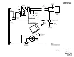
Page 51: ...Flaps Simplified Electrical Diagram Figure 19 OPERATING MANUAL 2A 27 00 Page 63 64 January 31 02 ...

Page 52: ...Flaps Horizontal Stabilizer System Hydraulic Control Diagram Figure 20 OPERATING MANUAL PRODUCTION AIRCRAFT SYSTEMS 2A 27 00 Page 65 January 31 02 Revision 6 ...

Page 53: ...Configuration Warning System Simplified Electrical Diagram Figure 21 OPERATING MANUAL PRODUCTION AIRCRAFT SYSTEMS 2A 27 00 Page 66 January 31 02 Revision 6 ...

Page 54: ... six spoiler panels extend automatically extend on touchdown to dump lift and increase braking effectiveness functioning as ground spoilers Panel function and position is summarized in the following table INPUT CONDITION PANEL POSITION Maximum Aileron No Speed Brakes Two Down Wing Flight Spoilers Extended 23 All Other Panels Retracted Maximum Speed Brakes No Aileron All Six Panels Extended 26 Maxi...

Page 55: ...to the actuator piston The pistons extends and the attached mechanical linkage drives all six spoiler panels to a position commensurate with SPEED BRAKE handle position Speed brake position is infinitely variable between fully retracted 0 and fully extended 26 2 depending on handle position With speed brakes extended rotation of the control wheel repositions the mechanical linkage between the aile...

Page 56: ...are retracted by selection of the GND SPLR switch to OFF Switch selection to OFF also causes a blue GND SPOILER UNARM advisory message to be displayed on CAS NOTE The GND SPLR switch is normally selected to ARMED on lineup before takeoff If either power lever is advanced above idle after the spoilers are armed the electrical circuit to the primary and secondary solenoid operated hydraulic control ...

Page 57: ... hydraulic signal that overrides any input to the servo valve through the SPEED BRAKE handle The override signal is supplied by Combined or Utility or Auxiliary hydraulic pressure to both actuators through normally closed solenoid valves Since the override signal is common to both the left and right actuators the possibility of asymmetrical extension is virtually eliminated In the unlikely event t...

Page 58: ...id operated hydraulic control valve nutcracker relay No 6 Failure of the secondary solenoid operated hydraulic control valve nutcracker relay No 1 Additionally the red GND SPOILER warning message will be displayed should any of the following events occur while on the ground Primary solenoid operated hydraulic control valve failure with the power levers not in ground idle Unlocked ground spoiler wi...

Page 59: ...out of idle f Retard the left power lever to idle Verify the following indications Ground spoilers remain stowed visually check NO GND SPOILERS light is extinguished GND SPOILER warning message is not displayed on CAS g Select the GND SPLR switch to OFF Verify the following indications GND SPOILER UNARM advisory message is displayed on CAS h Press and hold the GND SPLR TEST switch See Notes 2 and ...

Page 60: ...he cockpit The correct GND SPOILER message and NO GND SPOILERS light indications are sufficient for satisfactory preflight functional verification D Flight Power Shutoff System The flight power shutoff valve is a mechanically operated shutoff valve located between the Combined and Flight hydraulic system pressure sources and the flight and ground spoiler actuator pressure lines The valve consists ...

Page 61: ...andle SPEED BRAKE Handle Landing Gear Control Handle GND SPOILER GND SPOILER Failure of ground spoiler component or deployed ground spoiler panel Annunciation Cause or Meaning Red NO GND SPOILERS light on windshield center post Failure of ground spoiler component or deployed ground spoiler panel C Advisory Blue Messages and Annunciations CAS Message Cause or Meaning GND SPOILER UNARM Ground spoile...

Page 62: ...rsers are not used for landing See Section 05 17 50 Landing With Standby Electrical Power System Operating B Other Operational Information 1 Speed Brake Operating Envelope Speed brake operation is permitted within the flight envelope up to and including VMO MMO 2 Speed Brake Operating Altitude The use of speed brakes at altitudes below 2 000 feet AGL is not recommended 3 Effects of Speed Brake Ope...

Page 63: ...OPERATING MANUAL THIS PAGE IS INTENTIONALLY LEFT BLANK PRODUCTION AIRCRAFT SYSTEMS 2A 27 00 Page 76 January 31 02 ...

Page 64: ...Spoiler Control System Simplified Electrical Diagram Figure 22 OPERATING MANUAL 2A 27 00 Page 77 78 January 31 02 ...

Page 65: ...Spoiler Speed Brake Controls and Indications Figure 23 OPERATING MANUAL 2A 27 00 Page 79 80 January 31 02 ...

Page 66: ...Ground Spoiler Controls and Indications Figure 24 OPERATING MANUAL 2A 27 00 Page 81 82 January 31 02 ...
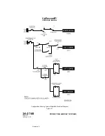
Page 67: ...Spoiler Speed Brake Control System Simplified Block Diagram Figure 25 OPERATING MANUAL PRODUCTION AIRCRAFT SYSTEMS 2A 27 00 Page 83 January 31 02 Revision 6 ...

Page 68: ...sition and the elevator to the trailing edge down position allows the gust lock to engage and lock the flight controls as their linkages reach the locking position Releasing the trigger and then lowering the GUST LOCK handle releases the gust lock Safety features prevent the gust lock from inadvertently engaging or a failure of the system preventing gust lock release With the gust lock released th...

Page 69: ...n wind gusts up to 60 knots CAUTION ENSURE HYDRAULIC PRESSURE IS DEPLETED PRIOR TO ENGAGING GUST LOCK CYCLE THE CONTROLS WITH THE CONTROL COLUMN CONTROL WHEEL AND RUDDER PEDALS TO DEPLETE ANY RESIDUAL PRESSURE OPERATING MANUAL PRODUCTION AIRCRAFT SYSTEMS 2A 27 00 Page 85 January 31 02 Revision 6 ...

Page 70: ...GUST LOCK Handle Figure 26 OPERATING MANUAL PRODUCTION AIRCRAFT SYSTEMS 2A 27 00 Page 86 January 31 02 Revision 6 ...

Reviews: