spoiler actuator. This allows the two outboard spoiler panels on the same
side as the raised aileron to extend commensurate with the amount of roll
input, up to a maximum of 23
±
2°. The opposite spoilers remain flush to the
wing as that aileron travels downward.
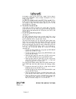
If the speed brakes are extended, the flight spoilers may extend up to a
maximum of 55 +4/-3°. The opposite spoilers remain in the position
commanded as speed brakes.
B. Speed Brake System:
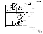
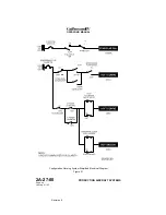
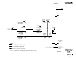
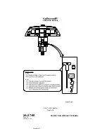
(See Figure 23 and Figure 25.)
The speed brake system provides a method for manual symmetrical
deployment of all six spoiler panels in flight to decrease airspeed and
increase descent rate. They may also be manually extended on the ground
to increase braking effectiveness, should the ground spoilers not
automatically extend upon landing or an aborted takeoff. This is
accomplished by mechanical control of the left and right flight spoiler
actuators through the use of the SPEED BRAKE handle located on the
cockpit center pedestal. The speed brake system is solely a hydraulically
powered system, thus reversion to manual control is not possible.
Moving the SPEED BRAKE handle out of the RETRACT detent provides
simultaneous mechanical input to the left and right flight spoiler mixing
linkages. Each mixing linkage then shifts the associated flight spoiler
actuator servo control valve to the extend position. The servo control valve
then directs Combined and Flight hydraulic system pressure to the actuator
piston. The pistons extends and the attached mechanical linkage drives all
six spoiler panels to a position commensurate with SPEED BRAKE handle
position. Speed brake position is infinitely variable between fully retracted
(0°) and fully extended (26
±
2°), depending on handle position.
With speed brakes extended, rotation of the control wheel repositions the
mechanical linkage between the aileron and flight spoiler control
mechanisms. Movement in either direction will further extend the outboard
two (inboard and outboard flight spoiler) panels on the side of the raised
aileron, up to a maximum of 55 +4/-3°. These panels will return to their
original speed-brakes-extended position when the control wheel is returned
to neutral.
When speed brakes are extended, a blue SPD BRAKE EXTNDED
advisory message is displayed on the Crew Alerting System (CAS). In
addition, the SPEED BRAKE handle will illuminate blue.
Should the fault warning computer and flight guidance computer disagree
on the position of the speed brakes, a blue SPD BRAKE SWITCH advisory
message is displayed on CAS.
A red ACFT CONFIGURATION warning message will be displayed on
CAS, along with the associated warning tone, whenever the SPEED
BRAKE handle is not in the RETRACT detent and the following conditions
occur:
•
Advancing either power lever above 80% HP RPM on the ground
•
Extending the flaps to DOWN (39°) or extending the landing gear in
flight
For aircraft having a Standby Warning Lights Panel (SWLP) installed, a red
ACFT CONFIG light will be illuminated whenever the SPEED BRAKE
OPERATING MANUAL
PRODUCTION AIRCRAFT SYSTEMS
2A-27-00
Page 68
January 31/02
Revision 6
Summary of Contents for IV
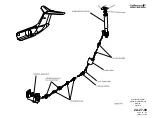
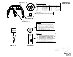
Page 17: ...Pitch Trim Controls Figure 5 OPERATING MANUAL 2A 27 00 Page 21 22 January 31 02 ...
Page 32: ...Rudder Pedals Forward Linkage Figure 13 OPERATING MANUAL 2A 27 00 Page 39 40 January 31 02 ...
Page 50: ...Flaps Simplified Block Diagram Figure 18 OPERATING MANUAL 2A 27 00 Page 61 62 January 31 02 ...

