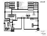
reed switches monitor actuator output in response to the input.
If a disagreement occurs between control column input and actuator
output, the associated limit switch and reed switch close to complete a
circuit to the respective hydraulic shutoff delay relay. If the relay remains
energized for more than ½ second, it energizes the respective hydraulic
shutoff control relay. The control relay in turn powers its hydraulic shutoff
valve to the closed position. Activation of the shutoff valve also causes an
amber EL CMB HYD OFF (or EL FLT HYD OFF) message to be displayed
on CAS.
3. Controls and Indications:
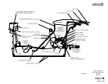
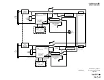
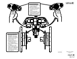
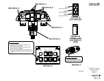
(See Figure 6 and Figure 7 through Figure 9.)
A. Circuit Breakers (CBs):
Circuit Breaker Name:
CB Panel:
Location:
Power Source:
SHAKER #1
CPO
A-10
Essential DC Bus
SHAKER #2
CPO
B-10
R Main DC Bus
STALL BARR DUMP
VALVE
CPO
A-8
Essential DC Bus
STALL BARR VALVE #1
CPO
A-12
Essential DC Bus
STALL BARR VALVE #2
CPO
B-12
R Main DC Bus
STALL BARRIER #1
CPO
A-9
Essential DC Bus
STALL BARRIER #2
CPO
B-9
R Main DC Bus
STALL WARN CMPTR #1
CPO
A-11
Essential DC Bus
STALL WARN CMPTR #2
CPO
B-11
R Main DC Bus
ELEV COMB HYD S/O (1)
CPO
B-15
Essential DC Bus
ELEV FLT HYD S/O (1)
CPO
A-15
Essential DC Bus
ELEV TRIM TAB ACTR
HTR (2)
CP
L-9
L Main AC Bus,
φ
C
NOTE(S):
(1) CAA certified aircraft only.
(2) SN 1380 & subs; SN 1000 - 1379 having ASC 342.
B. Warning (Red) Messages and Annunciations:
Annunciation:
Cause or Meaning:
Red chevron illuminated on pilot’s /
copilot’s AOA indexer.
AOA for approach and landing is too
high.
C. Caution (Amber) Messages and Annunciations:
CAS Message:
Cause or Meaning:
AOA HEAT 1-2 FAIL
Angle of attack probe heater failed.
EL CMB HYD OFF (1)
The flight control automatic failure detection system has
shut off Combined hydraulic system pressure to the
elevator actuator.
EL FLT HYD OFF (1)
The flight control automatic failure detection system has
shut off Flight hydraulic system pressure to the elevator
actuator.
EL MISTRIM NOSE
UP/DN
Autopilot elevator trim out of trim in direction indicated.
OPERATING MANUAL
PRODUCTION AIRCRAFT SYSTEMS
2A-27-00
Page 14
January 31/02
Revision 6
Summary of Contents for IV
Page 17: ...Pitch Trim Controls Figure 5 OPERATING MANUAL 2A 27 00 Page 21 22 January 31 02 ...
Page 32: ...Rudder Pedals Forward Linkage Figure 13 OPERATING MANUAL 2A 27 00 Page 39 40 January 31 02 ...
Page 50: ...Flaps Simplified Block Diagram Figure 18 OPERATING MANUAL 2A 27 00 Page 61 62 January 31 02 ...


